2-p0505-0560-ca2_enü@ü@ü@38 / 57
10ĢbīŃé╔BOOKé╠āyü[āWé╔ł┌ō«éĄé▄éĘ
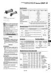
Symbol Double acting type, without cushion Type Fluid Action Proof pressure Maximum operating pressure Ambient and fluid temperature Minimum operating pressure Piston speed Cushion Stroke length tolerance Mounting Note) Intermediate strokes not listed above are produced upon receipt of order. Bore size (mm) Standard stroke (mm)Note) Long stroke (L and F only) 40 50, 63 80, 100 Symbol J K Rod boot material Nylon tarpaulin Heat resistant tarpaulin Max. ambient temperature 70üŗC 110üŗC . Mounting Standard equipment Options Rod end nut Clevis pin Single knuckle joint Double knuckle joint (With pin) With rod boot Basic style Rod side flange style Axial foot style Head side flange style Single clevis style Double clevis style Center trunnion style Caution Minimum Stroke for Auto Switch Mounting 1. The minimum stroke for mounting varies with the auto switch type and mounting style of the cylinder. In particular, the center trunnion style needs careful attention. (For more information, please refer to pages 555 and 556.) Accessory Rod Boot Material Setting Selection Bore size (mm) 40 50 63 80 100 (mm) -XAŁ -XC6 -XC14 -XC15 Change of rod end shape Piston rod and rod end nut made of stainless steel Change of trunnion bracket mounting position Change of tie-rod length Symbol Specifications Calculation: (Example) CA2LH40-100 (Axial foot style, o40, 100 st) . Basic weight ...............1.08 kg . Additional weight ........ 0.22/50 st . Cylinder stroke ...........100 st 1.08 + 0.22 x 100/50 = 1.52 kg . Values inside the parentheses are those for the steel tube type. Air-hydro Cylinder: Air-hydro Type Series CA2ŁH Double Acting, Single Rod Specifications Standard Stroke/ In case of a type with auto switch, also refer to the table of minimum strokes for auto switch mounting on pages 555 and 556. 25, 50, 75, 100, 125, 150, 175, 200, 250, 300, 350, 400, 450, 500 25, 50, 75, 100, 125, 150, 175, 200, 250, 300, 350, 400, 450, 500, 600 25, 50, 75, 100, 125, 150, 175, 200, 250, 300, 350, 400, 450, 500, 600, 700 800 1200 o80: 1400 o100: 1500 . Maximum ambient temperature for the rod boot itself. Made to Order Specifications (For details, refer to pages 1675 to 1818.) Note) Since a heavy duty scraper (-XC4) is installed as standard, there is no need to specify it. Weight/Aluminum Tube (Steel tube) (kg) Bore size (mm) Basic weight Additional weight per each 50 mm stroke Basic style Axial foot style Flange style Single clevis style Double clevis style Trunnion style All mounting brackets (Except steel tube trunnion) Steel tube trunnion Single knuckle Double knuckle (With pin) Accessory 40 50 63 80 100 0.89 (0.94) 1.08 (1.13) 1.26 (1.30) 1.12 (1.17) 1.16 (1.21) 1.25 (1.35) 0.22 (0.28) (0.36) 0.23 0.37 1.36 (1.40) 1.58 (1.62) 1.81 (1.86) 1.70 (1.74) 1.79 (1.83) 1.84 (1.94) 0.28 (0.35) (0.46) 0.26 0.43 2.00 (2.04) 2.34 (2.38) 2.79 (2.84) 2.63 (2.67) 2.79 (2.83) 2.80 (3.00) 0.37 (0.43) (0.65) 0.26 0.43 3.48 (3.63) 4.15 (4.30) 4.93 (5.08) 4.59 (4.74) 4.88 (5.03) 5.03 (5.32) 0.52 (0.70) (0.86) 0.60 0.87 4.87 (5.07) 5.86 (6.06) 6.79 (6.99) 6.65 (6.86) 7.17 (7.38) 7.15 (7.54) 0.65 (0.87) (1.07) 0.83 1.27 Precautions Caution 1. Do not use the cylinder near fire or on equipment or machinery whose ambient temperature exceeds 60üŗC. Since the air-hydro cylinder uses flammable hydraulic fluid, there is danger of potential fire. Caution 1. Keep the air-hydro cylinder load at 50% or less than the theoretical output. For the air-hydro cylinder to achieve performance that is close to that of the hydraulic cylinder in constant-speed operation and stopping accuracy, the load must be kept at 50% or less than theoretical output. . Minimum auto switch mounting stroke . Proper auto switch mounting position (detection at stroke end) and mounting height . Operating range . Auto switch mounting bracket: Part no. Refer to pages 553 to 558 for cylinders with auto switches. Air-hydro Turbine oil 5 to 60üŗC 0.1 MPa 0.5 to 300 mm/s Without 1.5 MPa 1.0 MPa Basic style, Foot style, Rod side flange style, Head side flange style, Single clevis style, Double clevis style, Center trunnion style Double acting to 250 st : 251 to 1000 st : 1001 to 1500 st : + 1.4 0 + 1.8 0 + 1.0 0 541 CJ1 CJP CJ2 -Z CJ2 CM2 -Z CM2 CM3 CG1 -Z CG1 CG3 MB -Z MB MB1 CA2 -Z CA2 CS1 CS2 D-« -X« Technical data