2-p0505-0560-ca2_enĀ@Ā@Ā@36 / 57
10ēbĆ„ā…BOOKāŐÉyĀ[ÉWā…ąŕďģāĶā‹ā∑
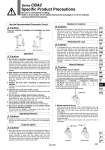
W W Use the Recommended Pneumatic Circuit. Series CBA2 Specific Product Precautions Be sure to read before handling. Refer to front matter 57 for Safety Instructions and pages 3 to 12 for Actuator and Auto Switch Precautions. Caution They are required to engage and disengage the locks correctly. Head side end lock Rod side end lock Caution Caution Caution Operation Operating Pressure 1. Supply air pressure of 0.15 MPa or higher to the port on the side that has the lock mechanism, as it is necessary for disengaging the lock. Exhaust Speed 1. When the pressure on the side with the lock mechanism drops to 0.05 MPa or below, the lock engages automatically. If the piping on the side with the lock mechanism is thin and long, or if the speed controller is away from the cylinder port, the lock engagement may take some due to decline of the exhaust speed. The same result will be caused by clogging of the silencer installed at the EXH port of the solenoid valve. 1. Do not use a 3 position solenoid valve. Avoid using this cylinder in combination with a 3 position solenoid valve (particularly the closed center metal seal type). If air pressure becomes sealed inside the port on the side that contains the lock mechanism, the lock will not engage. Even if the lock is engaged at first, the air that leaks from the solenoid valve could enter the cylinder and cause the lock to disengage as time elapses. 2. Back pressure is required when releasing the lock. Before starting, make sure that air is supplied to the side that is not equipped with a lock mechanism as shown in the diagram above (or the side on which the piston rod is unlocked, if both sides are equipped with a lock). Otherwise, the lock may not disengage. 3. Release the lock when mounting or adjusting the cylinder. The lock may not disengage if the cylinder is installed with its lock engaged. 4. Operate with a load ratio of 50% or less. The lock may not disengage or may become damaged if the load exceeds 50%. 5. Do not operate multiple synchronized cylinders. Avoid applications in which two or more end lock cylinders are synchronized to move one work piece, as one of the cylinder locks may not be disengaged when required. 6. Use a speed controller with meter-out control. If operated under meter-in control, the lock may not disengage. 7. Be sure to operate completely to the cylinder stroke end on the side with the lock. The lock may not engage or disengage if the piston in the cylinder has not reached the stroke end. Caution Caution Caution Relation to Cushion 1. When the cushion valve on the side with the lock mechanism is fully closed or almost closed, the piston rod may not be able to reach the stroke end, resulting in lock engagement failure. Furthermore, if the lock becomes engaged while the cushion valve is almost fully closed, it may become impossible to be disengaged. Therefore, the cushion valve must be adjusted properly. Releasing the Lock 1. To disengage the lock, make sure to supply air pressure to the port on the side without a lock mechanism, thus preventing the load from being applied to the lock mechanism. (Refer to the recommended air pressure circuit.) If the lock is disengaged, while the port on the side without a lock mechanism is in the exhausted state and the load is being applied to the lock mechanism, undue force may be applied to the lock mechanism, causing the lock mechanism to be damaged. Also, it could be extremely dangerous, because the piston rod could move suddenly. Manual Release 1. Non-lock type manual release Insert the bolt, which is provided as an accessory part, through the rubber cap (it is not necessary to remove the rubber cap). Screw the bolt into the lock piston and pull the bolt to disengage the lock. Releasing the bolt will re-engage the lock. The bolt size, pulling force, and the stroke are listed below. . Remove the bolt for normal operation. . It can cause lock malfunction or faulty release. Bore size (mm) 40, 50, 63 80, 100 Thread size M3 x 0.5 x 30 L or more M5 x 0.8 x 40 L or more Pulling force 10 N 24.5 N Stroke (mm) 3 3 Rubber cap 2. Manual release lock type Push the M/O knob and turn it 90Āč counterclockwise. The lock disengages when the ūą mark on the cap is aligned with the ūČ OFF mark on the M/O knob (and the lock will remain disengaged). To engage the lock, push the M/O knob all the way in and turn it 90Āč clockwise to align the ūą mark on the cap with the ūČ ON mark on the M/O knob. At this time, make sure that the knob stops by clicking into place. Failure to click it into place properly can cause the lock to disengage. Lock Release Lock state Release state 539 CJ1 CJP CJ2 -Z CJ2 CM2 -Z CM2 CM3 CG1 -Z CG1 CG3 MB -Z MB MB1 CA2 -Z CA2 CS1 CS2 D-ūģ -Xūģ Technical data