2-p0505-0560-ca2_en 35 / 57
10秒後にBOOKのページに移動します
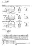
With rod boot 40 50 63 80 100 (mm) Stroke range (mm) 20 to 500 20 to 600 20 to 600 20 to 750 20 to 750 Bore size (mm) e 43 52 52 65 65 d 56 64 64 76 76 f 11.2 11.2 11.2 12.5 14 h 59 66 66 80 81 ZZ 154 167 178 213 224 With Rod Boot l 1/4 stroke 1/4 stroke 1/4 stroke 1/4 stroke 1/4 stroke Dimensions of the mounting brackets are the same as those of the standard double acting single rod type. Refer to pages 513 to 517. H1 DL G oE HR B C N HN DL oMO oRF WL E G oD K F AL A N H M Manual release (Non-lock type): Suffix L Manual release (Non-lock type): Suffix N MM J HR B C oRF WL E J H1 HN DL oMO DL G oE N G oD K F AL A N H M MM H1 DL G DL G oE HR B C N HN DL oMO oRF WL E oD K F AL A N H M J MM ZZ + l + Stroke od 10.2 l f oe h + l Series CBA2 Basic Style (Dimensions are common to rear end lock, front end lock and double end lock types.) Head side end lock: CBA2B S + Stroke ZZ + Stroke Width across flats of hexagon hole WB 2 x cushion valve Width across flats KA Width across flats B1 2 x P (Rc, NPT, G) Rod side end lock: CBA2B Bore size Stroke -RN Bore size Stroke -WN Manual release (Lock type): Suffix L Manual release (Non-lock type): Suffix N S + Stroke ZZ + Stroke Width across flats of hexagon hole WB 2 x cushion valve Width across flats KA Width across flats B1 2 x P (Rc, NPT, G) Double lock: CBA2B Manual release (Lock type): Suffix L Manual release (Non-lock type): Suffix N Width across flats B1 S + Stroke ZZ + Stroke Width across flats of hexagon hole WB 2 x cushion valve Width across flats KA 2 x P (Rc, NPT, G) Stroke range 40 50 63 80 100 Up to 500 Up to 600 Up to 600 Up to 750 Up to 750 A 30 35 35 40 40 AL 27 32 32 37 37 60 70 85 102 116 B B1 22 27 27 32 41 C 44 52 64 78 92 D 16 20 20 25 30 13 13 15.5 18.5 20 DL E 32 40 40 52 52 F 10 12 10 14 14 G 15 17 17 21 21 H 51 58 58 71 72 8 11 11 13 16 H1 HR 42.3 47.3 54.8 65.8 72.8 56 61 68.5 80.5 87.5 J M8 x 1.25 M8 x 1.25 M10 x 1.25 M12 x 1.75 M12 x 1.75 6 7 7 11 11 K KA 14 18 18 22 26 M 11 11 14 17 17 MM M14 x 1.5 M18 x 1.5 M18 x 1.5 M22 x 1.5 M26 x 1.5 MO 19 19 19 23 23 N 27 30 31 37 40 RF 17 17 17 21 21 84 90 98 116 126 S 2.5 2.5 4 4 4 WB WL 25 25 25 40 40 ZZ 146 159 170 204 215 Bore size (mm) HN (MAX) P 1/4 3/8 3/8 1/2 1/2 . For more information about the rod end nut and accessories, refer to page 519. Bore size Stroke -HN 538