2-p0505-0560-ca2_en 32 / 57
10秒後にBOOKのページに移動します
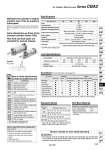
Symbol Air cushion Bore size (mm) 40 50 63 80 100 Fluid Proof pressure Maximum operating pressure Minimum operating pressure Ambient and fluid temperature Piston speed Cushion Stroke length tolerance Lubrication Mounting -XA -XB6 -XC3 -XC4 .1 -XC6 .1 -XC7 -XC8 .1 -XC9 .2 -XC10 -XC14 -XC15 -XC22 -XC27 -XC28 -XC29 -XC35 .1 Change of rod end shape Heat resistant (150°C) Special port position With heavy duty scraper Piston rod, rod end nut made of stainless steel Tie-rod, cushion valve, tie rod nut, etc. made of stainless steel Adjustable stroke/Extension adjustment Adjustable stroke/Retraction adjustment Dual stroke/Double rod Change of trunnion bracket mounting position Change of tie-rod length Fluororubber seal Double clevis pin and double knuckle pin made of stainless steel Compact flange made of SS400 Double knuckle joint with spring pin With coil scraper Symbol Specifications .1: For head side end lock type only .2: For rod side end lock type only Air Cylinder: With End Lock Series CBA2 Maintains the cylinder’s original position even if the air supply is interrupted. Same dimensions as those of the standard cylinder (Series CA2) Non-lock and lock types are standard for manual release. When air is discharged at the stroke end position, the lock engages to maintain the rod in that position. Accessory/For more information, refer to page 519. Lock Specifications Lock position Holding force (Max.) (N) Backlash Manual release Head side end, Rod side end, Double end 2 mm or less Non-lock type, Lock type o40 860 o50 1340 o63 2140 o80 3450 o100 5390 Accessory Mounting Basic style Axial foot style Rod side flange style Head side flange style Single clevis style Double clevis style. Center trunnion style Standard Rod end nut Clevis pin Lock release bolt (N type only) Single knuckle joint Double knuckle joint (With pin) Rod boot Option . Double clevis and double knuckle joint types are packed with pin, cotter pin and flat washer. . 0.05 MPa except locking parts. Standard Stroke Bore size (mm) 40 50, 63 80, 100 Standard stroke (mm) 25, 50, 75, 100, 125, 150, 175, 200, 250, 300, 350, 400, 450, 500 25, 50, 75, 100, 125, 150, 175, 200, 250, 300, 350, 400, 450, 500, 600 25, 50, 75, 100, 125, 150, 175, 200, 250, 300, 350, 400, 450, 500, 600, 700 . Types with auto switch have different minimum strokes. Please refer to pages 555 and 556. Rod Boot Material Symbol J K Rod boot materials Nylon tarpaulin Heat resistant tarpaulin Max. ambient temperature 70°C 110°C. . Maximum ambient temperature for the rod boot itself. Caution Minimum Stroke for Auto Switch Mounting 1. The minimum stroke for mounting varies with the auto switch type and mounting style of the cylinder. In particular, the center trunnion style needs careful attention. (For more information, please refer to pages 555 and 556.) Made to Order Specifications (For details, refer to pages 1675 to 1818.) . Minimum auto switch mounting stroke . Proper auto switch mounting position (detection at stroke end) and mounting height . Operating range . Auto switch mounting bracket: Part no. Refer to pages 553 to 558 for cylinders with auto switches. Specifications Air 1.5 MPa 1.0 MPa 0.15 MPa. Without auto switch: .10 to 70°C (With no freezing) With auto switch: .10 to 60°C (With no freezing) 50 to 500 mm/s Interchangeable Not required (Non-lube) Basic style, Axial foot style, Rod side flange style, Head side flange style, Single clevis style, Double clevis style, Center trunnion style to 250 st : 251 to 1000 st : 1001 to 1500 st : + 1.4 0 + 1.8 0 + 1.0 0 535 CJ1 CJP CJ2 -Z CJ2 CM2 -Z CM2 CM3 CG1 -Z CG1 CG3 MB -Z MB MB1 CA2 -Z CA2 CS1 CS2 D- -X Technical data