2-p0505-0560-ca2_en 27 / 57
10秒後にBOOKのページに移動します
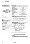
Bore size (mm) 40 50 63 Minimum Stroke for Auto Switch Mounting Non-rotating accuracy: ±0.8° Same mounting dimensions as those of standard cylinder Bore size (mm) 40 50, 63 Standard stroke (mm) 25, 50, 75, 100, 125, 150, 175, 200, 250, 300, 350, 400, 450, 500. 25, 50, 75, 100, 125, 150, 175, 200, 250, 300, 350, 400, 450, 500, 600. Production of Types with Rod Boot (kg) Bore size (mm) 40 1.01 1.20 1.38 1.37 0.27 0.23 0.37 50 1.54 1.76 1.99 2.02 0.36 0.26 0.43 63 2.17 2.50 2.96 2.97 0.42 0.26 0.43 Accessory Basic style Axial foot style Flange style Trunnion style Single knuckle Double knuckle (with pin) Basic weight Additional weight per each 50 mm stroke Fluid Proof pressure Maximum operating pressure Minimum operating pressure Ambient and fluid temperature Piston speed Cushion Stroke length tolerance Rod non-rotating accuracy Allowable rotational torque Lubrication Mounting . With no freezing. Series CA2KW is also available with rod boot. Please consult with SMC for more information. -XC7 -XC14 -XC15 -XC28 Tie-rod, cushion valve, tie rod nut, etc. made of stainless steel Change of trunnion bracket mounting position Change of tie-rod length Compact flange made of SS400 Symbol Specifications Series CA2KW Specifications Standard Stroke/ In case of a type with auto switch, also refer to the table of minimum strokes for auto switch mounting on pages 555 and 556. . Intermediate strokes not listed above are also available. Please consult with SMC for longer strokes than the strokes marked with “.”. Weight/Aluminum Tube Calculation: (Example) Weight CA2KWL40-100 . Basic weight ・・・・・・・・・・・・・・・1.20 (Axial foot style o40) . Additional weight ・・・・・・・・0.27/50 st . Cylinder stroke・・・・・・・・・・・ 100 st 1.20 + 0.27 x 100/50 = 1.74 kg Caution 1. The minimum stroke for mounting varies with the auto switch type and mounting style of the cylinder. In particular, the center trunnion style needs careful attention. (For more information, please refer to pages 555 to 556.) Symbol . Minimum auto switch mounting stroke . Proper auto switch mounting position (detection at stroke end) and mounting height . Operating range . Auto switch mounting bracket: Part no. Refer to pages 553 to 558 for cylinders with auto switches. Made to Order Specifications (For details, refer to pages 1675 to 1818.) Air 1.5 MPa 1.0 MPa 0.08 MPa Without auto switch: .10 to 70°C With auto switch: .10 to 60°C. 50 to 500 mm/s Air cushion ±0.8° 0.44 N・m or less Not required (Non-lube) Basic style, Axial foot style, Rod side flange style, Head side flange style, Center trunnion style to 250 st : 251 to 600 st : + 1.4 0 + 1.0 0 530