2-p0403-0451-mb_en@@@44 / 50
10bÐèBOOKäy[WèÖÛçÉñ
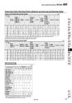
Proper Auto Switch Mounting Position (Detection at stroke end) and Mounting Height Proper Auto Switch Mounting Position Bore size Auto switch model D-A9ÞÙ D-A9ÞÙV D-M9ÞÙ D-M9ÞÙV D-M9ÞÙW D-M9ÞÙWV D-M9ÞÙA D-M9ÞÙAV 6.5 6.5 7 7 10 10 12 32 40 50 63 80 100 125 4 4 4.5 4.5 8.5 8.5 12 10.5 10.5 11 11 14 14 16 8 8 8.5 8.5 12.5 12.5 16 D-A5ÞÙ D-A6ÞÙ A 0.5 0.5 1 1 4 4 6 B 0 0 0 0 2.5 2.5 6 D-A59W A 4.5 4.5 5 5 8 8 10 B 2 2 2.5 2.5 6.5 6.5 10 D-F5ÞÙW D-J59W D-F5ÞÙ D-J5ÞÙ D-F5BA D-F59F A 7 7 7.5 7.5 10.5 10.5 12.5 B 4.5 4.5 5 5 9 9 12.5 D-F5NT A 12 12 12.5 12.5 15.5 15.5 17.5 B 9.5 9.5 10 10 14 14 17.5 D-A3ÞÙ D-A44 D-G39 D-K39 A 0.5 0.5 1 1 4 4 6 B 0 0 0 0 2.5 2.5 6 D-Z7ÞÙ D-Z80 D-Y59ÞÙ D-Y69ÞÙ D-Y7P D-Y7PV D-Y7ÞÙW D-Y7ÞÙWV D-Y7BA A 4 4 4.5 4.5 7.5 7.5 9.5 B 1.5 1.5 2 2 6 6 9.5 D-P3DW A 6 6 6 6 4 4 6.5 B 3 3 4 4 2.5 2.5 6.5 D-P4DW A 3.5 3.5 4 4 7 7 9 B 1 1 1.5 1.5 5.5 5.5 9 A B A B (mm) Proper Auto Switch Mounting Height Bore size Auto switch model 32 40 50 63 80 100 125 D-M9ÞÙV D-M9ÞÙWV D-M9ÞÙAV Hs Ht D-A9ÞÙV Hs Ht D-A9ÞÙ D-M9ÞÙ D-M9ÞÙW D-M9ÞÙA 24.5 28.5 33.5 38.5 46.5 54 65.5 Hs 23 25.5 31 36 45 53.5 64.5 27.5 31.5 36 40.5 49 57 68.5 23 25.5 31 36 45 53.5 64.5 30.5 34 38.5 43 52 59.5 71 23 25.5 31 36 45 53.5 64.5 D-A5ÞÙ D-A6ÞÙ D-A59W Hs 35 38.5 43.5 48.5 55 62 71.5 Ht 24.5 27.5 34.5 39.5 46.5 55 66.5 D-F5ÞÙ D-J5ÞÙ D-F59F D-F5ÞÙW D-J59W D-F5BA D-F5NT Hs 32.5 36.5 41 46 52.5 59.5 70.5 Ht 25 27.5 34 39 46.5 55 66.5 D-A3ÞÙ D-G39 D-K39 Hs 67 71.5 77 83.5 92.5 103 115 Ht 27.5 27.5 . . . . . D-A44 Hs 77 81.5 87 93.5 103 113.5 125 Ht 27.5 27.5 . . . . . D-Z7ÞÙ D-Z80 D-Y59ÞÙ D-Y7P D-Y7ÞÙW D-Y7BA Hs 25.5 29.5 33.5 39 47.5 55.5 67.5 Ht 23 26 31 36 45 53.5 65 D-Y69ÞÙ D-Y7PV D-Y7ÞÙWV Hs 26.5 30 34.5 40 48.5 56.5 68.5 Ht 23 26 31 36 45 53.5 65 D-P3DW Hs 34 38 42 50 56 63.5 74.5 Ht 23 26 31 36 45 53.5 64.5 D-P4DW Hs 38 42 46.5 51.5 58 65.5 76.5 Ht 31 33 39 44 51.5 60.5 72 Ht (mm) D-F5ÞÙ/J5ÞÙ D-F5ÞÙW/J59W D-F5BA/F5NT D-F59F D-G39/K39 D-P3DW D-P4DW D-Y59ÞÙ/Y69ÞÙ D-Y7P/Y7ÞÙV D-Y7ÞÙW/Y7ÞÙWV D-Y7BA Operating Range Auto switch model Bore size 32 7 4 7.5 9 13 9 5.5 3.5 9 4.5 4 40 7.5 4.5 8.5 9 13 9 5.5 4 9 5 4 50 8.5 5 7.5 10 13 10 7 4 9 5 4 63 9.5 6 9.5 11 14 11 7.5 4.5 10 5.5 4.5 80 9.5 6 9.5 11 14 11 6.5 4.5 10 4 4 100 10.5 6 10.5 11 15 11 5.5 4.5 11 6.5 4.5 125 12 7 13 10 17 10 7 5 11 8.5 4.5 D-A9ÞÙ/A9ÞÙV D-Z7ÞÙ/Z80 D-A5ÞÙ/A6ÞÙ D-A59W D-A3ÞÙ/A44 D-M9ÞÙ/M9ÞÙV D-M9ÞÙW/M9ÞÙWV D-M9ÞÙA/M9ÞÙAV (mm) . Cylinders without an air cushion have different dimensions for proper auto switch mounting positions (A and B). Add the following values to both A and B: 3 mm (o 32 and 40), 4 mm (o50 and 63), 5 mm (o80 and 100), 6 mm (o125). Note) Adjust the auto switch after confirming the operating conditions in the actual setting. . Since this is a guideline including hysteresis, not meant to be guaranteed. (Assuming approximately }30% dispersion.) There may be the case it will vary substantially depending on an ambient environment. Auto Switch Mounting Series MB 445 CJ1 CJP CJ2 -Z CJ2 CM2 -Z CM2 CM3 CG1 -Z CG1 CG3 MB -Z MB MB1 CA2 -Z CA2 CS1 CS2 D-ÞÛ -XÞÛ Technical data