2-p0403-0451-mb_en 39 / 50
10秒後にBOOKのページに移動します
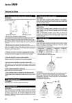
W W Locking style Turn 90° to counterclockwise pushing M/O button. Lock is released when 傣 on cap and 傈 OFF mark on M/O button correspond. (Lock remains released.) When locking is desired, turn M/O button clockwise 90° while pushing fully, correspond 傣 on cap and 傈 ON mark on M/O button. The correct position is confirmed by click sound “click”. If not confirmed, locking is not done. Locked Released Lock Release Rubber cover With locking at head side With locking at rod side Cautions for Using For correct operation of the locking and release mechanism, please use the following pneumatic circuit. 1. Use recommended pneumatic circuit Caution Avoid using circuit with 3 position solenoid valve (especially closed center). When pressure is trapped in the port with locking mechanism, end lock is free. When utilizing a 3 position closed center valve, even if the lock is engaged, it may become unlocked due to pressure leakage either across the piston or the valve spool. q Do not use a 3 position solenoid valve. Be sure air is supplied to side of cylinder without the locking mechanism, as above, prior to supplying air pressure to the side with end lock or lock may not be released. (Refer to “Release of lock”.) w Back pressure is required to release end lock. If mounting is done with lock engaged, lock mechanism may be damaged. e Release lock when mounting or adjusting the cylinder. If cylinder is used at 50% load capacity or more, lock may be damaged. r Use with load 50% or less of rated capacity. Avoid to using 2 or more end lock cylinders at same time to perform a single task because binding may occur and one of the cylinders end lock may not release. t Do not use two cylinders in parallel at same time. Meter-in control may not allow lock to release. y Use a speed controller as meter-out. If cylinder piston does not reached end of stroke, end lock may not lock or release. u Use complete stroke or cylinder at side with end lock. Use pressures over 0.15 MPa at port with locking mechanism. 2. Operating pressure When pressures at port with locking mechanism is decrease to 0.05 MPa or less, it is automatically locked. When exhaust pipe at port with locking mechanism is thin and long or speed controller is separated from cylinder port, exhaust speed is slow and will require additional time for lock engagement. Clogging the silencer mounted on exhaust port of solenoid valve leads to same result. 3. Exhaust speed Caution Caution When cushion valve at side with locking mechanism is fully opened or closed, piston rod may reached at stroke end. Thus lock is not established. And when locking is done at cushion valve fully closed, adjust cushion valve since lock may not be released. 4. Relationship with cushion When lock is to be released, supply air pressure to the port without the locking mechanism, this relieves the load from the lock mechanism. Then supply pressure to the port with lock, releasing the lock and changing cylinder direction. (Refer to recommended pneumatic circuit.) When port without lock mechanism is exhausted and locking mechanism is loaded, the lock may be damaged due to excessive force on lock during release. Piston rod will operate immediately. 5. Release of lock Non-locking type Insert attached bolt from upper side of rubber cover (no need to remove rubber cover), tighten locking piston and pull bolt, locking will be released. When bolt is released, locking begins to take place. Thread size, required pulling force and stroke are listed below. 6. Manual release Bore size (mm) 32 40, 50, 63 80, 100 Thread size . M2.5 x 0.45 x 25 L . M3 x 0.5 x 30 L . M5 x 0.8 x 40 L Pulling force 4.9 N 10 N 24.5 N Stroke (mm) 2 3 3 . Remove bolt under normal operations. It may cause malfunction of locking and release. Caution Warning Caution Series MBB 440