2-p0403-0451-mb_en 38 / 50
10秒後にBOOKのページに移動します
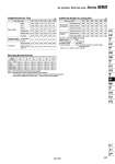
Weight/Aluminum Tube Bore size (mm) Basic Foot Flange Single clevis Double clevis Trunnion Single knuckle Double knuckle (with pin) 32 0.50 0.68 0.79 0.75 0.76 0.79 0.15 0.22 40 0.69 0.93 1.06 0.92 0.96 1.05 0.23 0.37 50 1.19 1.56 1.64 1.53 1.62 1.67 0.26 0.43 63 80 2.73 3.61 4.18 3.84 4.13 4.28 0.60 0.87 3.7 4.8 7.01 6.87 7.39 7.37 0.83 1.27 100 Basic weight Additional weight per each 50 mm stroke Accessory All mounting bracket 0.11 0.16 0.26 1.47 1.93 2.26 2.1 2.26 2.27 0.26 0.43 0.27 0.42 0.56 (kg) Additional Weight of Locking Part Bore size (mm) Locking at head end (H) Locking at rod end (R) Locking at both ends (W) Locking at head end (H) Locking at rod end (R) Locking at both ends (W) 32 0.08 0.08 0.16 0.09 0.09 0.18 40 0.13 0.13 0.26 0.15 0.15 0.30 50 0.21 0.20 0.41 0.23 0.22 0.45 63 0.30 0.29 0.59 0.32 0.31 0.63 80 0.75 0.71 1.46 0.78 0.74 1.52 100 1.1 1.03 2.13 1.13 1.06 2.19 Manual release non-locking (N) Calculation example: MBBL32-100-HN 傱 Basic weight ・・・・・・・・・・・・・・・ 0.68 傱 Additional weight ・・・・・・・・ 0.11/50 stroke 傱 Cylinder stroke ・・・・・・・・・・・ 100 stroke 傱 Locking weight ・・・・・・・・・・・ 0.08 (Locking at head end, manual release non-locking type) 0.68 + 0.11 x 100/50 + 0.08 = 0.98 kg (kg) Manual release locking (L) Mounting Bracket Part No. 32 MB-L03 MB-F03 MB-C03 MB-D03 40 MB-L04 MB-F04 MB-C04 MB-D04 50 MB-L05 MB-F05 MB-C05 MB-D05 63 MB-L06 MB-F06 MB-C06 MB-D06 80 MB-L08 MB-F08 MB-C08 MB-D08 100 MB-L10 MB-F10 MB-C10 MB-D10 Note 1) Two foot brackets required for one cylinder. Note 2) Accessories for each mounting bracket are as follows: Foot, flange, single clevis/body mounting bolt, double clevis/body mounting bolt, clevis pins, flat washer and cotter pins. → Refer to page 416 for details. Foot Flange Single clevis Double clevis Note 1) Bore size (mm) Air Cylinder: With End Lock Series MBB 439 CJ1 CJP CJ2 -Z CJ2 CM2 -Z CM2 CM3 CG1 -Z CG1 CG3 MB -Z MB MB1 CA2 -Z CA2 CS1 CS2 D-𡱖 -X𡱖 Technical data