2-p0403-0451-mb_en 31 / 50
10秒後にBOOKのページに移動します
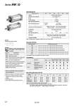
Bore size (mm) Action Direction of low friction Fluid Proof pressure Max. operating pressure Min. operating pressure Ambient and fluid temperature Lubrication Cushion Port size (Rc, NPT, G) Mounting Allowable leakage Double acting single rod One direction Note 1) Air 1.05 MPa 0.7 MPa Without auto switch: .10 to 70°C (No freezing) With auto switch: .10 to 60°C (No freezing) Not required (Non-lube) None 0.01 MPa (o40 to o100) 0.025 MPa (o32) 0.5 L/min (ANR) or less 32 40 50 63 80 100 Basic, Foot, Rod side flange, Head side flange, Single clevis, Double clevis, Center trunnion Note 1) Please refer to Selection Guide for the Low Friction Side. 1/8 1/4 3/8 1/2 Specifications Symbol Double acting, Without cushion Made to Order Specifications (For details, refer to pages 1675 to 1818.) -XA -XC3 -XC6 -XC7 -XC14 -XC27 -XC29 -XC30 Change of rod end shape Special port position Piston rod and rod end nut made of stainless steel Tie rod, cushion valve, tie rod nut, etc. made of stainless steel Change of trunnion bracket mounting position Double clevis pin and double knuckle pin made of stainless steel Double knuckle joint with spring pin Rod side trunnion Symbol Specifications Refer to pages 444 to 449 for cylinders with auto switches. . Minimum stroke for auto switch mounting . Proper auto switch mounting position (detection at stroke end) and mounting height . Operating range . Auto switch mounting bracket: Part no. Intermediate strokes are available. (No spacer is used.) Mounting Bracket Part No. 32 MB-L03 MB-F03 MB-C03 MB-D03 40 MB-L04 MB-F04 MB-C04 MB-D04 50 MB-L05 MB-F05 MB-C05 MB-D05 63 MB-L06 MB-F06 MB-C06 MB-D06 80 MB-L08 MB-F08 MB-C08 MB-D08 100 MB-L10 MB-F10 MB-C10 MB-D10 Note 1) Two foot brackets required for one cylinder. Note 2) Accessories for each mounting bracket are as follows: Foot, flange, single clevis/body mounting bolt, double clevis/body mounting bolt, clevis pins, flat washer and cotter pins. → Refer to page 416 for details. Foot Flange Single clevis Double clevis Note 1) Bore size (mm) Accessory Mounting Standard Stroke 32 40 50 63 80 100 Bore size (mm) 25, 50, 75, 100, 125, 150, 175, 200, 250, 300, 350, 400, 450, 500 25, 50, 75, 100, 125, 150, 175, 200, 250, 300, 350, 400, 450, 500 25, 50, 75, 100, 125, 150, 175, 200, 250, 300, 350, 400, 450, 500, 600 25, 50, 75, 100, 125, 150, 175, 200, 250, 300, 350, 400, 450, 500, 600 25, 50, 75, 100, 125, 150, 175, 200, 250, 300, 350, 400, 450, 500, 600, 700, 800 25, 50, 75, 100, 125, 150, 175, 200, 250, 300, 350, 400, 450, 500, 600, 700, 800 Standard stroke (mm) Center trunnion Double clevis Single clevis Head side flange Rod side Basic flange . Rod end nut Clevis pin Single knuckle joint Double knuckle joint (With pin) Standard Option Foot . . . . . Series MBQ 432