2-p0403-0451-mb_enБ@Б@Б@26 / 50
10ХbМуВ╔BOOKВ╠ГyБ[ГWВ╔И┌УоВ╡В▄В╖
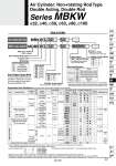
Mounting B L F G T Basic/Without bracket Axial foot Rod side flange Head side flange Center trunnion With auto switch Double rod Non-rotating Rod Type Rod boot/Cushion Cylinder stroke (mm) Refer to page 428 for standard strokes. Bore size 32 40 50 63 80 100 32 mm 40 mm 50 mm 63 mm 80 mm 100 mm Port thread type Nil TN TF Rc NPT G L L 32 32 50 Non-rotating Rod Type 50 None Nylon tarpaulin (head or rod end) Nylon tarpaulin (both ends) Heat resistant tarpaulin (head or rod end) Heat resistant tarpaulin (both ends) Both ends None Nil J JJ K KK Nil N. Rod boot Cushion . Model without air cushion is designed to include rubber bumpers. The overall length is longer than the cylinder with air cushions because the bumpers are attached to the both sides of the piston as follows. o32, o40: +6 mm, o50, o63: +8 mm, o80, o100: +10 mm M9BW MBKW MDBKW With auto switch (Built-in magnet) Built-in Magnet Cylinder Model If a built-in magnet cylinder without an auto switch is required, there is no need to enter the symbol for the auto switch. (Example) MDBKB40-100 . Lead wire length symbols: 0.5 mБcБcБcБcБcNil (Example) M9NW 1 mБcБcБcБcБcM (Example) M9NWM 3 mБcБcБcБcБcL (Example) M9NWL 5 mБcБcБcБcБcZ (Example) M9NWZ . Solid state auto switches marked with a БgЁ╖Бh are produced upon receipt of order. . Besides the above models, there are some other auto switches that are applicable. For detailed information, please refer to page 449. . Solid state auto switches are also available with a pre-wired connector. Refer to pages 1626 and 1627 for details. Refer to pages 1614 and 1615 for D-P3DWЁн. . D-A9Ён/M9ЁнЁнЁн/P3DWЁн auto switches are shipped together (not assembled). (However, auto switch mounting brackets are assembled for D-A9Ён/M9ЁнЁнЁн when being shipped.) M9N M9P M9B J51 . . M9NW M9PW M9BW M9NA.. M9PA.. M9BA.. F59F P3DW P4DW . . . . G39 K39 . . . . . . . . . . 100V,200V . ЁЧ ЁЧ ЁЧ ЁЧ . . ЁЧ ЁЧ ЁЧ Ё╖ Ё╖ Ё╖ ЁЧ ЁЧ . ЁЧ ЁЧ ЁЧ ЁЧ . . ЁЧ ЁЧ ЁЧ ЁЧ ЁЧ ЁЧ ЁЧ ЁЧ ЁЧ ЁЧ ЁЧ ЁЧ . . . ЁЧ ЁЧ ЁЧ Ё╖ Ё╖ Ё╖ . . . Ё╖ Ё╖ Ё╖ Ё╖ . . Ё╖ Ё╖ Ё╖ Ё╖ Ё╖ Ё╖ Ё╖ ЁЧ ЁЧ Ё╖ Ё╖ Ё╖ . . . Ё╖ Ё╖ Ё╖ Ё╖ Ё╖ Ё╖ Ё╖ Ё╖ Ё╖ IC circuit . IC circuit . IC circuit . IC circuit . 5V,12V 12V . 5V,12V 12V 5V,12V 12V 5V,12V 12V 5V,12V . Grommet 3-wire (Equiv. to NPN) 2-wire (Non-polar) . 2-wire 24V Yes Yes No Yes No Terminal conduit DIN terminal Grommet 5V . Relay, PLC PLC Relay, PLC 12V . Diagnostic indication (2-color indication) A96 A93 A90 A54 A64 . . . A59W . . . . . A33 A34 A44 . . 100V 100V or less 100V,200V 200V or less . 100V,200V . ЁЧ ЁЧ ЁЧ ЁЧ ЁЧ . . . ЁЧ ЁЧ ЁЧ ЁЧ ЁЧ ЁЧ . . . ЁЧ . . . . . . . . . . ЁЧ . ЁЧ . . . . . . . . . . . . . . IC circuit . IC circuit . . 24V . 24V 3-wire(NPN) 3-wire(PNP) 2-wire 3-wire(NPN) 2-wire 3-wire(NPN) 3-wire(PNP) 2-wire 3-wire(NPN) 3-wire(PNP) 2-wire 4-wire(NPN) Yes Grommet Terminal conduit Grommet Relay, PLC . Type Special function Electrical entry Load voltage Wiring (Output) Pre-wired connector Applicable load DC AC Auto switch model Lead wire length (m) Tie-rod mounting Band mounting 0.5 (Nil) 3 (L) 5 (Z) 1 (M) Applicable Auto Switches/Refer to pages 1559 to 1673 for further information on auto switches. .. Water resistant type auto switches can be mounted on the above models, but in such case SMC cannot guarantee water resistance. Consult with SMC regarding water resistant types with the above model numbers. Number of auto switches Nil S 3 n 2 1 3 n Made to Order For details, refer to page 428. Auto switch Nil Without auto switch . For applicable auto switches, refer to the table below. How to Order Series MBKW o32, o40, o50, o63, o80, o100 Air Cylinder: Non-rotating Rod Type Double Acting, Double Rod Indicator light Reed auto switch Solid state auto switch Diagnostic indication (2-color indication) Water resistant (2-color indication) Magnetic field resistant (2-color indication) Diagnostic output (2-color indication) 427 CJ1 CJP CJ2 -Z CJ2 CM2 -Z CM2 CM3 CG1 -Z CG1 CG3 MB -Z MB MB1 CA2 -Z CA2 CS1 CS2 D-Ёо -XЁо Technical data