2-p0403-0451-mb_en 23 / 50
10秒後にBOOKのページに移動します
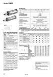
Symbol Double acting, Air cushion Specifications Bore size (mm) Action Fluid Proof pressure Max. operating pressure Min. operating pressure Ambient and fluid temperature Lubrication Operating piston speed Allowable stroke tolerance Cushion Note 1) Port size (Rc, NPT, G) Mounting Double acting, Single rod Air 1.5 MPa 1.0 MPa 0.05 MPa Without auto switch: .10 to 70°C (No freezing) With auto switch: .10 to 60°C (No freezing) Not required (Non-lube) 50 to 1000 mm/s up to 250: , 251 to 1000: , 1001 to 1500: Both ends (Air cushion) Basic, Foot, Rod side flange, Head side flange, Single clevis, Double clevis, Center trunnion 32 40 50 63 80 100 1/8 1/4 3/8 1/2 Non-rotating accuracy Allowable rotating torque N・m max. ±0.5° ±0.5° ±0.3° 0.25 0.45 0.64 0.79 0.93 +1.0 0 +1.4 0 +1.8 0 Note 1) Absorbable kinetic energy by cushion mechanism is identical to double acting single rod. When requesting a cylinder without air cushion, cylinder utilizes rubber bumpers which increases cylinders overall length. Accessory Mounting Standard Option Rod end nut Clevis pin Single knuckle joint Double knuckle joint (with pin) Rod boot Basic Foot Rod side flange Head side flange Single clevis Double clevis Center trunnion . . . . . . Weight/Aluminum Tube Bore size (mm) Basic weight Basic Foot Flange Single clevis Double clevis Trunnion All mounting bracket Single knuckle Double knuckle (with pin) 32 0.50 0.62 0.79 0.75 0.76 0.79 0.11 0.15 0.22 Add’l weight per each 50 mm stroke Accessory 40 0.66 0.83 1.03 0.89 0.93 1.02 0.15 0.23 0.37 50 1.21 1.41 1.64 1.55 1.64 1.69 0.26 0.26 0.43 63 1.51 1.75 2.30 2.14 2.30 2.31 0.27 0.26 0.43 80 2.58 3.23 4.03 3.69 3.98 4.13 0.40 0.60 0.87 100 3.73 4.36 7.04 6.90 7.42 7.40 0.52 0.83 1.27 (kg) Calculation example: MBKB32-100 (Basic, o32, 100 st) Basic weight ・・・・・・・・・・・・ 0.50 (Basic o32) Additional weight ・・・・・ 0.11/50 stroke Cylinder stroke ・・・・・・ 100 stroke 0.50 + 0.11 x 100/50 = 0.72 kg Refer to pages 444 to 449 for cylinders with auto switches. . Minimum stroke for auto switch mounting . Proper auto switch mounting position (detection at stroke end) and mounting height . Operating range . Auto switch mounting bracket: Part no. Made to Order Specifications (For details, refer to pages 1675 to 1818.) -XA -XC3 -XC6 -XC7 -XC8 -XC9 -XC10 -XC14 -XC27 -XC30 Change of rod end shape Special port position Piston rod and rod end nut made of stainless steel Tie rod, cushion valve, tie rod nut, etc. made of stainless steel Adjustable stroke cylinder/Adjustable extend stroke Adjustable stroke cylinder/Adjustable retract stroke Dual stroke cylinder/Double rod Change of trunnion bracket mounting position Double clevis pin and double knuckle pin made of stainless steel Rod side trunnion Symbol Specifications Standard Stroke 32 40 50 63 80 100 25, 50, 75, 100, 125, 150, 175, 200, 250, 300, 350, 400, 450, 500 25, 50, 75, 100, 125, 150, 175, 200, 250, 300, 350, 400, 450, 500 25, 50, 75, 100, 125, 150, 175, 200, 250, 300, 350, 400, 450, 500, 600 25, 50, 75, 100, 125, 150, 175, 200, 250, 300, 350, 400, 450, 500, 600 25, 50, 75, 100, 125, 150, 175, 200, 250, 300, 350, 400, 450, 500, 600, 700, 800 25, 50, 75, 100, 125, 150, 175, 200, 250, 300, 350, 400, 450, 500, 600, 700, 800 Intermediate strokes are available. (No spacer is used) Bore size (mm) Standard stroke (mm) Series MBK 424