1-p2001-2010-vt307_en 6 / 11
10秒後にBOOKのページに移動します
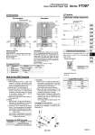
1 2 Voltage 100 VAC 200 VAC DC Others Color Blue Red Red (+), Black (.) Gray Terminal no. DIN terminal 1 2 + . Description DIN connector Part no. B1B09-2A (Standard) GM209NJ-B17 (CE-compliant) Connector for DIN Terminal How to Use DIN Terminal 1. Disassembly 1) After loosening the screw q, then if the housing w is pulled in the direction of the screw q, the connector will be removed from the body of equipment (solenoid, etc.). 2) Pull the screw q out of the housing w. 3) On the bottom part of the terminal block e, there’s a cut-off part o. If a small flat head screwdriver is inserted between the opening in the bottom, terminal block e will be removed from the housing w. 4) Remove the cable gland r, plain washer t and rubber seal y. 2. Wiring 1) Pass the cable u through the cable gland r, plain washer t and rubber seal y in this order, and then insert them into the housing w. 2) Loosen the screw !1 attached to the terminal block e. Then, pass the lead wire !0 through the terminal block e and tighten the screw !1 again. Note 1) Tighten within the tightening torque of 0.5 N・m ±15%. Note 2) Cable u outside diameter: o6 to o8 mm Note 3) Crimped terminal like round-shape or Y-shape cannot be used. 3. Assembly 1) Pass the cable u through the cable gland r, plain washer t and rubber seal y in this order and connect to the terminal block e. Then, mount the terminal block e on the housing w. (Push it down until you hear the click sound.) 2) Put the rubber seal y and plain washer t in this order into the cable entry of the housing w, and then tighten the cable gland r securely. 3) Insert the gasket i between the bottom part of terminal block e and the plug attached to the equipment. Then, screw in q from the top of the housing w to tighten it. Note 1) Tighten within the tightening torque of 0.5 N・m ±20%. Changing the entry direction The orientation of a connector can be changed 180°, depending on the combination of a housing w and a terminal block e. De-energized Energized Light/Surge Voltage Suppressor Caution Electrical Connection Lead Wire Color DIN terminal is connected inside as in the figure below. Connect to the corresponding power supply. DIN terminal block ・ Applicable cable O.D. o6 to o8 Construction Terminal no. 2 Coil Terminal no. 1 Terminal no. 2 (.) Coil Terminal no. 1 (+) In the case of indicator light assembly In the case of indicator light assembly 1 2 3 4 No. Description Material Aluminum die-casted Aluminum, HNBR Stainless steel Body Poppet valve Return spring Molded coil Resin Note Color: White Operation principle