1-p1917-1927-v100_en 8 / 12
10秒後にBOOKのページに移動します
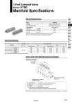
Manifold Specifications Series V100 3 Port Solenoid Valve Manifold Specifications How to Order Valve Manifold Assembly (Example) Ordering example Flow Characteristics Manifold Port size Port 1, 2, 3 Type VV100-S41 V114 V114A V124 V124A M5 x 0.8 Note) Values when mounted on the manifold base (5 stations). Valve (N.C.) Stations ...... 5 4 3 2 1 Manifold base (5 stations) VV100-S41-05-M5 V114-5GZ Blanking plate assembly V100-77-1A 1→2 Flow characteristics 2→3 C[dm3/(s.bar)] 0.032 0.070 0.050 0.085 b 0.13 0.10 0.26 0.16 Cv 0.007 0.016 0.012 0.020 C[dm3/(s.bar)] 0.050 0.085 0.032 0.070 b 0.26 0.16 0.13 0.10 Cv 0.012 0.020 0.007 0.016 1 2 2 3 Model Manifold P (SUP)/R (EXH) style Valve stations Output port porting specifications Port size Type S41 Location Direction Port 1, 2, 3 Single base style/B mount Common SUP/Common EXH 2 to 20 stations Base Side M5 x 0.8 Note 1) V114(A) and V124(A) cannot be mounted to the same manifold. Note 2) For V124(A), pressure from port 3 and exhaust from port 1. VV100-S41-05-M5 1 set (Type S41, 5 station manifold base part no.) .V100-77-1A 1 set (Blanking plate assembly part no.) .V114-5GZ 4 sets (Valve) .The asterisk (.) is used when referring to assembly. Enter the asterisk at the beginning of individual component part numbers. Beneath the manifold base part number, enter the valve and option part numbers to be mounted. 1923 VV100 VV061 V100 S070 VQD VQD-V VKF VK VT VS4 VS3