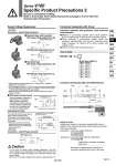
Red (+) Black (.) Polarity protection diode Coil LED Red (+) Black (.) Polarity protection diode Coil (.,+) (+,.) Varistor Coil LED (.,+) (+,.) Varistor Coil Electric circuit (with power saving circuit) For Single Solenoid (‾) (‾) Varistor Coil LED Black 2 1 (.) Red (+) 1: Starting current, 2: Holding current Coil Diode Timer circuit L Surge Voltage Suppressor Grommet, L and M Plug Connector Connector Assembly with Cover How to Order SY100 - 68 - A - Lead wire length (L) Nil 6 10 15 20 25 30 50 300 mm 600 mm 1000 mm 1500 mm 2000 mm 2500 mm 3000 mm 5000 mm Connector Assembly with Cover/Dimensions 傜 Standard type (with polarity) With surge voltage suppressor (屟S) With light/surge voltage suppressor (屟Z) 傜 Non-polar type With surge voltage suppressor (屟R) With light/surge voltage suppressor (屟U) Operating Principle 12 Applied voltage Standard With power saving circuit 62 ms 24 V 0 V 0.4 W 0.1 W 0 W 傜 With power saving circuit Grommet, L and M Plug Connector With light (屟Z) In the case of varistor surge voltage suppressor, note the surge voltage to be suppressed at controller side as there will be a residual voltage according to the protective element and rated voltage. Moreover, the residual voltage of the diode is approximately 1 V. Caution Power consumption is reduced by approximately 75% compared with the standard product by eliminating the need for electrical current for holding. (Effective after more than 62 ms energized and 24 VDC rated voltage applied.) The electrical circuit as shown above, allows reduced holding current consumption and measures power saving. Refer to the electric waveform on the right. . Please be careful not to reverse the polarity, since a diode to prevent the reversed current is not provided for the power saving circuit. . Please connect correctly the lead wires to + (positive) and . (negative) indications on the connector. . For DC voltages other than 12, 24 VDC, incorrect wiring will cause damage to the surge voltage suppressor circuit since a diode to prevent reverse current is not provided. (Wrong polarity will cause trouble.) . Solenoids, whose lead wires have been pre-wired: positive side red and negative side black. Connector assembly with protective cover enhances dust protection 傱 Effective in preventing possible short circuit problems due to contaminants in contact with connector section. 傱 Cover material is chloroprene rubber which has excellent weatherability and electric insulation properties. However, be careful not to allow contact with cutting oil, etc. 傱 Round cord provides neat appearance. Symbol for a connector assembly with cover . No need to indicate the part number for a connector assembly with cover in this case. 傱 How to Order Indicate part number of connector assembly with cover in addition to the solenoid valve part number without connector of the plug connector. Lead wire length: 2000 mm V114-5LOZ-M5 SY100-68-A-20 Lead wire length: 300 mm (Standard) V114-5LPZ-M5 Red Black Gray (14.5) (40) (10) (8) (8) (6.9) (o4.1) Connector Connector Series V100 Specific Product Precautions 2 Be sure to read before handling. Refer to front matter 53 for Safety Instructions and pages 3 to 8 for 3/4/5 Port Solenoid Valve Precautions. 1927 VV100 VV061 V100 S070 VQD VQD-V VKF VK VT VS4 VS3 A
