1-p1585-1683-vfr2000_enБ@Б@Б@95 / 100
10ХbМуВ╔BOOKВ╠ГyБ[ГWВ╔И┌УоВ╡В▄В╖
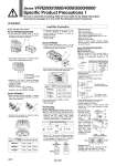
Ground + - - - w q + - - - e w B side solenoid Common (COM) terminal A side solenoid q (Jumper bar) COM(+) 1 A 2 3 B 4 . + + . 7 mm or less 7 mm or less 4 mm or more Ground 4 mm or more A side B side B side terminal block A side terminal block Terminal block Model marking VFR510Ён VFR520Ён 3 VFR540Ён 5 A. (1) A side A side A side B+ (3) COM COM COM B. (4) B side B side Position Model Left A side A side A side Center COM COM COM Right B side B side VFR610Ён VFR620Ён 3 VFR640Ён 5 Terminal no. Internal wiring SOL. A side SOL. B side COM Ground 1 2 3 Series VFR2000/3000/4000/5000/6000 Specific Product Precautions 1 Be sure to read before handling. Refer to front matter 53 for Safety Instructions Instructions and pages 3 to 8 for 3/4/5 Port Solenoid Valve Precautions. Black (.) Red (+) Diode Varistor Caution Lead Wire Connection . If you remove the junction cover q on the sub-plate, you will see the plug-in terminal block w attached to the inside of sub-plate. Series VFR2000/3000/4000 Plug-in type (With terminal block) . The following markings are on the terminal block. Connect with corresponding power side. . Although БgA.Бh, БgB+Бh and БgB.Бh marks are indicated on the terminal block, this can be used as either Бg+COMБh or Бg.COMБh. . Applicable terminal: VFR2000, VFR3000: 1.25-3, 1.25-3S, 1.25Y-3N, 1.25Y-3S VFR4000: 1.25-3.5M, 1.25Y-3L, 1.25Y-3M . Remove junction cover for sub-plate q, depress levers e of terminal block assembly w, pull out terminal block assembly. Series VFR5000 . Terminal block assembly is marked as below. Connect it to power supply side. . Terminal block assembly can be used as Бg+Бh and Бg.Бh common regardless of markings. Do not remove jumper bar because it is used for common connection. . Applicable terminal: 1.25-4, 1.25-4M Series VFR6000 . If you remove the junction cover q on the sub-plate, you will see the plug-in terminal block w attached to the inside of sub-plate. . Terminal block assembly is wired like the following figure. Connect it to each power supply side. . Can be used as either Бg+COMБh or Бg.COMБh. . Applicable terminal: 1.25-4, 1.25-4M Non plug-in type Series VFR2000 Series VFR3000/4000 (VFR3Ён40/4Ён40) . Type G: Lead wire comes directly from the solenoid part. Connect it with the power source. Grommet with DC voltage surge voltage suppressor has polarity. Connect red lead wire to + (positive) side and black to . (negative) side. Surge voltage suppressor DC AC . Type E, T, D, Y: In the case of DIN terminal block and terminal block, there is no polarity of positive [+] and negative [.]. Connect no. 1 and no. 2 terminals with corresponding power side. With DIN terminal block With terminal block Coil Coil . Applicable cable O.D. Type T: o6 to o8 mm Type E: o2.3 to o2.8 mm Type D (Series VFR2000): o6 to o8 mm Type D (Series VFR3000/4000): o4.5 to o7 mm Type Y: o4.5 to o7 mm . Applicable crimp terminal Type E, T: 1.25-3, 1.25-3S, 1.25Y-3N, 1.25Y-3S (Round shape or Y shape crimp terminal cannot be used for Type D.) Series VFR3000/4000/5000/6000 (VFR3Ён10/4Ён10) DIN terminal block type . Male pin terminal of DIN terminal block of solenoid valves are wired as shown below. Connect to corresponding terminal on the connector. . Can be used as either Бg+COMБh or Бg.COMБh. . Applicable cable Cross section of the wire: 0.5 to 1.5 mm2 Cable O.D.: o8 to o10 . Applicable crimp terminal shown below. Corresponding to R1.25-3 of JIS C 2805 J.S.T. Mfg. Co., Ltd. Equivalent to R1.25-3 . Applicable terminal: VFR3000: 1.25-3, 1.25-3S, 1.25Y-3N, 1.25Y-3S VFR4000: 1.25-3.5M, 1.25Y-3L, 1.25Y-3M VFR5000/6000: 1.25-3.5M, 1.25-3L, 1.25-3M . Proper tightening torque of the connector Connector set screw 0.5 to 0.6 NБEm Terminal screw 0.5 to 0.6 NБEm . Incorrect connection of БgCOM terminalБh (DIN terminal no. 3) can cause damage on power source circuit. Terminal block type . Remove cover q, over terminal block w attached to the inside of body. Connect with corresponding power side. For a style with light and surge voltage suppressor, straightly pull out the light and surge voltage suppressor substrate e and then connect them. 1678