1-p1585-1683-vfr2000_en 7 / 100
10秒後にBOOKのページに移動します
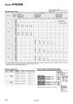
System A B E Average speed (mm/s) 800 700 600 500 400 300 200 100 0 800 700 600 500 400 300 200 100 0 800 700 600 500 400 300 200 100 0 D 800 700 600 500 400 300 200 100 0 C 800 700 600 500 400 300 200 100 0 Bore size Series CM Pressure 0.5 MPa Load factor 50% Stroke 300 mm Series MB, CA2 Pressure 0.5 MPa Load factor 50% Stroke 500 mm Series CS1/CS2 Pressure 0.5 MPa Load factor 50% Stroke 1000 mm o20 o25 o32 o40 o40 o50 o63 o80 o100 o125 o140 o160 . It is when the cylinder is extending that is meter-out controlled by speed controller which is directly connected with cylinder, and its needle valve with being fully open. . The average velocity of the cylinder is what the stroke is divided by the total stroke time. . Load factor: ((Load mass x 9.8)/Theoretical force) x 100% Perpendicular, upward actuation Horizontal actuation System Solenoid valve Speed controller Silencer Tube bore x Length A B C D E Series VFR2000 Rc 1 8 Series VFR2000 Rc 1 4 AS2000-01 AN110-01 AS3000-02 AN110-01 AS3000-02 AN110-01 AS4000-02 AN110-01 AS4000-02 AN110-01 T0425 x 1 m T0604 x 1 m T0806 x 1 m T1075 x 1 m T1209 x 1 m Plug-in Non plug-in