1-p1585-1683-vfr2000_en 63 / 100
10秒後にBOOKのページに移動します
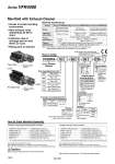
Plug-in type Non plug-in type Exhaust cleaner (Option) Exhaust cleaner (Option) U side D side Manifold with Exhaust Cleaner . Serves to protect working environment. . Valve exhaust noise dampening: 35 dB or more. . Collection rate of drainage and oil mist: 99.9% or more. . Piping work is reduced. How to Order Manifold Specifications Manifold Wiring Applicable valve model VFR4尰0尰-尰F(-Q) VFR4尰1尰-尰D(-Q) VFR4尰1尰-尰E VFR4尰4尰-尰G, VFR4尰4尰-尰E VFR4尰4尰-尰T, VFR4尰4尰-尰D(-Q) Porting specifications Applicable exhaust cleaners Stations A, B port P port Plug-in type: VV5FR4-01尰(-Q) Non plug-in type: VV5FR4-10(-Q) Non plug-in type: VV5FR4-40(-Q) With terminal block With multi-connector With D-sub connector DIN terminal Grommet terminal Grommet, Grommet terminal, Conduit terminal, DIN terminal Common SUP, Common EXH 2 to 10 stations (With multi-connector/D-sub connector: 2 to 8 stations) AMC610-10 (Port size: R 1), AMC810-14 (Port size: R 11/2) (1) Note 1) Use “AMC810-14” when used with 5 or more stations or in high frequency. Exhaust cleaner “AMC610-10” and “AMC810-14” are not attached. 10 06 1 03 CD Series VFR4000 Manifold Symbol Symbol 1 2 Side Bottom . Passage Porting specifications P EA, EB (A, B) Common Common . Semi-standard VV5FR4 Base type/Electrical entry Plug-in type with terminal block Plug-in type with multi-connector 01T 01C Plug-in type with D-sub connector Non plug-in type Common electrical entry Non plug-in type Individual electrical entry 01F 10 40 Symbol CD CU D side U side Exhaust cleaner mounting direction D side mounting U side mounting Symbol Applicable base D Nil U 01C, 01F 01T, 10, 40 With connector D side mounting None U side mounting Connector mounting direction 2 stations 10 stations 02 10 Note) Stations Note) . Base 01T/10/40: 2 to 10 stations . Base 01C/01F: 2 to 8 stations Port size Symbol P, EA, EB A, B . 03 04 M Mixed 1 2 1 2 3 8 . For bottom ported: Rc 3/8 only. Rc NPT Nil N T NPTF F G Thread type CE-compliant Q CE-compliant Nil . . Please indicate size or port size of exhaust cleaner. Side: 3/8, 1/2 Bottom: 3/8 (Option) Side: 1/2 EXH 1 11/2 Series VFR4000 Note) Electrical entry and light/surge voltage suppressor: D/DZ/DO/DOZ, Y/YZ/YO/YOZ, F, FZ only. Exhaust cleaner mounting direction Caution When using an exhaust cleaner, mount it downwards.