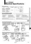
Terminal block Conduit wiring Multi-connector U side D side Manifold Specifications Base model Wiring . With terminal block . With multi-connector . With D-sub connector . Grommet terminal . DIN terminal Porting specifications Port size A, B port Side/Bottom A, B Stations 2 to 10 2 to 8 2 to 10 Applicable valve model VFR4尰0尰-尰F(-Q) VFR4尰1尰-尰E VFR4尰1尰-尰D(-Q) VFR4尰4尰-尰G VFR4尰4尰-尰E VFR4尰4尰-尰T VFR4尰4尰-尰D(-Q) Plug-in type VV5FR4-01尰(-Q) Non plug-in type VV5FR4-10(-Q) Non plug-in type VV5FR4-40(-Q) . Grommet . Grommet terminal . Conduit terminal . DIN terminal P, EA, EB 1 2 3 8, 1 2 Plug-in type with terminal block: 6 stations Non plug-in type: 6 stations How to Order Manifold Assembly VV5FR4-01T-061-03 (-Q) 1 set (Manifold base part no.) .VFR4100-5FZ (-Q) 3 sets (2 position single part no.) .VFR4200-5FZ (-Q) 2 sets (2 position double part no.) .VVFS4000-10A 1 set (Blanking plate assembly part no.) ・・・・・・・・・・・ ・・・・・・・・・・・・・・・・・・・・・ ・・・・・・・・・・・・・・・・・・・・・ ・・・・・・・・・・・・・・・・・・・・・・・・・・ The asterisk denotes the symbol for assembly. Prefix it to the part nos. of the solenoid valve, etc. Valve arrangement is counted from the D side. When ordering, specify the part nos. in order from the 1st. station in the D side. When entry of part numbers becomes complicated, indicate on the manifold specification sheet. Valve arrangement is counted from the D side. When ordering, specify the part nos. in order from the 1st. station in the D side. When entry of part numbers becomes complicated, indicate on the manifold specification sheet. VV5FR4-10-061-03 (-Q) 1 set (Manifold base part no.) .VFR4110-5D (-Q) 5 sets (2 position single part no.) .VFR4410-5D (-Q) 1 set (3 position exhaust center part no.) .VVFS4000-R-04-2 1 set (Individual EXH spacer part no.) The asterisk denotes the symbol for assembly. Prefix it to the part nos. of the solenoid valve, etc. VV5FR4 01T Plug-in type with terminal block 06 1 03 Series VFR4000 Manifold 2 stations 10 stations 02 10 Stations VV5FR4 01C Plug-in type with multi-connector D Series VFR4000 Manifold D side mounting U side mounting D U Connector mounting direction . Since lead wires of solenoid valve are connected with the terminals on upper surface of terminal block corresponding lead wires from power source can be wired at the bottom of terminal block. Plug-in Type: With Multi-connector (For wiring specifications, refer to page 1683.) . Master connection of power and solenoid valves. . Quick wiring permits ease of installation. Symbol Symbol 1 2 Side Bottom . Passage Porting specifications P EA, EB (A, B) Common Common . Semi-standard Rc NPT Nil N T NPTF F G Thread type Port size Symbol P, EA, EB A, B . 03 04 M Mixed 1 2 1 2 3 8 . For bottom ported: Rc 3/8 only. CE-compliant Plug-in Type: With Terminal Block 05 1 03 2 stations 8 stations 02 08 . Stations . Max: 8 stations Port size Symbol P, EA, EB A, B . 03 04 M Mixed 1 2 1 2 3 8 . For bottom ported: Rc 3/8 only. Rc NPT Nil N T NPTF F G Thread type Symbol Symbol 1 2 Side Bottom . Passage Porting specifications P EA, EB (A, B) Common Common . Semi-standard CE-compliant Series VFR4000 Manifold Specifications ・・・・・・・・・・・ ・・・・・・・・・・・・・・・・・・・・・ ・・・・・・・・・・・・・・・・・・・・・ ・・・・・・・・・・・・・・・・・・・・・ Q CE-compliant Nil . Q CE-compliant Nil . [Option] 1639 SY SJ SY SV SYJ SZ VF VP4 S0700 VQ VQ4 VQ5 VQC VQC4 VQZ SQ VFS VQ7 VFR