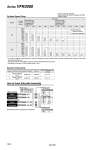
System A B Average speed (mm/s) 800 700 600 500 400 300 200 100 0 800 900 900 1000 1000 700 600 500 400 300 200 100 0 Bore size Series MB, CA2 Pressure 0.5 MPa Load factor 50% Stroke 500 mm Series CS1/CS2 Pressure 0.5 MPa Load factor 50% Stroke 1000 mm o40 o50 o63 o80 o100 o125 o140 o160 o180 o200 Cylinder Speed Chart System Solenoid valve Speed controller Silencer SPG (Steel pipe) dia. x Length 6A x 1 m 10A x 1 m Series VFR3000 Rc Series VFR3000 Rc A B AN20-02 AN30-03 AS4000-02 AS420-03 1 4 3 8 System Components Plug-in VFR3000 P Non plug-in VFS3000 S Plug-in Non plug-in Pilot type Nil R External pilot Internal pilot Piping port (P, A, B, EA, EB port) 02 Rc Note) Mounting bolts and gaskets are not attached. 1 4 Piping port (P, A, B, EA, EB port) 02 03 1 4 3 8 Thread type Nil F G N NPT T NPTF How to Order Sub-plate Assembly VFS3000 S B VFR3000 P B 02 02 02 02 Use as a guide for selection. Please confirm the actual conditions with SMC Sizing Program. Perpendicular, upward actuation Horizontal actuation Series VFR3000 . It is when the cylinder is extending that is meter-out controlled by speed controller which is directly connected with cylinder, and its needle valve with being fully open. . The average velocity of the cylinder is what the stroke is divided by the total stroke time. . Load factor: ((Load mass x 9.8)/Theoretical force) x 100% 1610