1-p1585-1683-vfr2000_en 21 / 100
10秒後にBOOKのページに移動します
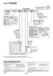
VV5FR2 10 Port size .2, .3 08 1 01 AP Series VFR2000 Manifold 2 stations 15 stations 02 15 Note) Stations Rc NPT Nil N T NPTF F G Symbol .2, .3 Thread type Symbol 1 Side 2 . Bottom 3 . Side 4 . Bottom 5 . Side 6 . Bottom 7 . Side 8 . Bottom Passage .1 Porting specifications P EA, EB (A, B) Common Common Common Individual Individual Common Individual Individual . Semi-standard . 1 When an individual passage is used, P, EA and EB ports will be bottom ported. . 2 For bottom ported, A/B port size is 1/8 (Symbol 01) only. . 3 Symbol “1” is only applicable to One-touch fittings (C6, C8). Note) . 01CD1, 01CU1, 01FD1, 01FU1: Max. 8 stations . 01T, 01T1, 10: Max. 15 stations . Including station of control unit Air release valve Control equipment Symbol Air filter regulator with manual drain Air filter regulator with auto-drain Pressure switch Blanking plate (Air release valve) Blanking plate (Filter regulator) Blanking plate (Pressure switch) Required stations 2 stations 1 station MP AP M A G F C E Note) Control unit is D side mounting only. Control unit type Base model Connector mounting direction Junction cover Symbol Electrical entry Plug-in type terminal block Plug-in type multi-connector 01T 01CD1 Stacking type Integrated type Integrated type D side U side 01T1 01CU1 Plug-in type D-sub connector Non plug-in type 01FD1 D side Integrated type 01FU1 U side 10 Symbol 01 02 C6 C8 P, EA, EB A, B One-touch fitting for o8 One-touch fitting for o6 M Mixed 1 4 1 4 1 8 VV5FR2-01T1-091-02-MP5 (-Q) 1 set (Manifold base part no.) .VFR2100-5FZ (-Q) 5 sets (2 position single part no.) .VFR2200-5FZ (-Q) 2 sets (2 position double part no.) The asterisk denotes the symbol for assembly. Prefix it to the part nos. of the solenoid valve, etc. The 1st and 2nd station are used for control unit mounting. When ordering, specify the part nos. in order from the 3rd. station in the D side. When entry of part numbers becomes complicated, indicate on the manifold specification sheet. The 1st and 2nd station are used for control unit mounting. When ordering, specify the part nos. in order from the 3rd. station in the D side. When entry of part numbers becomes complicated, indicate on the manifold specification sheet. VV5FR2-10-071-01-M5 (-Q) 1 set (Manifold base part no.) .VFR2110-5D (-Q) 5 sets (2 position single part no.) The asterisk denotes the symbol for assembly. Prefix it to the part nos. of the solenoid valve, etc.