1-p1585-1683-vfr2000_enü@ü@ü@100 / 100
10ĢbīŃé╔BOOKé╠āyü[āWé╔ł┌ō«éĄé▄éĘ
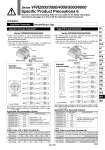
Connector terminal no. Connector terminal no. M2.6 x 0.45 D-sub connector Applicable plug assembly (Option) VVZS3000-21A-Ł Multi-connector Applicable plug assembly (Option) VVFS2000-30A-Ł Fig. (1) U side Manifold internal wiring Manifold internal wiring Assembly part no. Cable length VVZS3000-21A-1 VVZS3000-21A-2 VVZS3000-21A-3 VVZS3000-21A-4 . VVZS3000-21A-5 . VVZS3000-21A-6 . VVZS3000-21A-7 . 1.5 m 3 m 5 m 8 m 10 m 15 m 30 m VVZS3000-21A-8 . 20 m Component parts Plug MIL standard type D connector Number of terminals: 25 pins Cable: 25 cores x 0.3 mm2 . Option Applicable Plug Assembly (Option) . Except VFR5000 . Except VFR5000 Series VFR2000/3000/4000/5000/6000 Specific Product Precautions 6 Be sure to read before handling. Refer to front matter 53 for Safety Instructions Instructions and pages 3 to 8 for 3/4/5 Port Solenoid Valve Precautions. Caution Lead Wire Connection Manifold/Plug-in Type Type 01C Circular Connector Type 01F D-sub Connector Series VFR2000/3000/4000/5000 Series VFR2000/3000/4000/5000 Terminal no. Lead wire color Dot marking 1 Orange . 2 Orange Yes 3 Black . 4 Black Yes 5 Green . 6 Green Yes 7 Red . 8 Red Yes 9 Blue . 10 Blue Yes 11 Yellow . 12 Yellow Yes 13 Brown . Terminal no. Lead wire color Dot marking 14 Brown Yes 15 White . 16 White Yes 17 Pink . 18 Pink Yes 19 Gray . 20 Gray Yes 21 Sky blue . 22 Sky blue Yes 23 Light green . 24 Light green Yes Terminal no. Lead wire color Dot marking 1 Black . 2 Brown . 3 Red . 4 Orange . 5 Yellow . 6 Pink . 7 Blue . 8 Purple White 9 Gray Black 10 White Black 11 White Red 12 Yellow Red Terminal no. Lead wire color Dot marking 13 Orange Red 14 Yellow Black 15 Pink Black 16 Blue White 17 Purple . 18 Gray . 19 Orange Black 20 Red White 21 Brown White 22 Pink Red 23 Gray Red 24 Black White 25 White . Cable Color List of Each Terminal No. Cable Color List of Each Terminal No. Assembly part no. Cable length VVFS2000-30A-1 VVFS2000-30A-2 VVFS2000-30A-3 VVFS2000-30A-4 . VVFS2000-30A-5 . VVFS2000-30A-6 . VVFS2000-30A-7 . 1.5 m 3 m 5 m 7 m 10 m 15 m 20 m Component parts Plug 206837-1 1 pc. Cable clamp 206138-1 1 pc. Socket 66101-2 24 pcs. Cable VCTF 24 cores x 0.75 mm2 made by Tyco Electronics AMP K.K. . Option Applicable Plug Assembly (Option) . When multi-connector is used, mass-termination between power supply side and solenoid valve can be done. This saves the wiring connection labor. . Wire connection specifications Lead wire for both solenoid A and B sides in manifold are connected to connector terminal as COM specifications. . MIL standard type D connector (Terminal: 25 pins) has wide exchangeability and saves wiring labor. . Wire connection specifications Lead wire for both solenoid A and B sides in manifold are connected to connector terminal as COM specifications. Note 1) Maximum number is 8 stations. Note 2) It is used as +COM and .COM. Note 3) Station numbers are started from D side although connector is mounted on D or U Side. Note 1) Maximum number is 8 stations. Note 2) It is used as +COM and .COM. Note 3) Station numbers are started from D side although connector is mounted on D or U Side. D side Stations Fig. (2) U side D side Stations Connector terminal no. Connector terminal no. Pressure switch Air release valve 23 24 COM 22 SOL.B SOL.A 7 stations 20 21 COM 19 SOL.B SOL.A 6 stations 17 18 COM 16 SOL.B SOL.A 5 stations 14 15 COM 13 SOL.B SOL.A 4 stations 11 12 COM 10 SOL.B SOL.A 3 stations 897 COM SOL.B SOL.A 5 4 1 2 Max. 8 stations Max. 8 stations 23 24 COM 22 SOL.B SOL.A 7 stations 20 21 COM 19 SOL.B SOL.A 6 stations 17 18 COM 16 SOL.B SOL.A 5 stations 14 15 COM 13 SOL.B SOL.A 4 stations 11 12 COM 10 SOL.B SOL.A 3 stations 897 COM SOL.B SOL.A 2 stations 564 COM SOL.B SOL.A 1 station 231 COM SOL.B SOL.A Connector terminal no. Connector terminal no. Air release valve Pressure switch 24 12 COM 25 SOL.B SOL.A 7 stations 10 23 COM 11 SOL.B SOL.A 6 stations 21 9 COM 22 SOL.B SOL.A 5 stations 7 20 COM 8 SOL.B SOL.A 4 stations 18 6 COM 19 SOL.B SOL.A 3 stations 4 17 COM 5 SOL.B SOL.A 15 16 1 station 2 stations 2 stations 1 station 1 2 24 12 COM 25 SOL.B SOL.A 7 stations 10 23 COM 11 SOL.B SOL.A 6 stations 21 9 COM 22 SOL.B SOL.A 5 stations 7 20 COM 8 SOL.B SOL.A 4 stations 18 6 COM 19 SOL.B SOL.A 3 stations 4 17 COM 5 SOL.B SOL.A 2 stations 15 36 COM SOL.B SOL.A 1 station 1 14 COM 2 SOL.B SOL.A Max. 8 stations Max. 8 stations Control unit Control unit 1683 SY SJ SY SV SYJ SZ VF VP4 S0700 VQ VQ4 VQ5 VQC VQC4 VQZ SQ VFS VQ7 VFR