1-p1217-1252-vqc4000_en 32 / 36
10秒後にBOOKのページに移動します
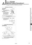
. Refer to page 1245 for pilot valve assembly part number. DC: Single DC: Double SOL SOL SOL LED: Orange . (+) +(.) COM: +(.) COM: +(.) B side LED: Green A side: . (+) B side: . (+) A side LED: Orange Caution Refer to front matters 42 to 45. Note) Coil surge voltage generated when OFF is about -60V. Please contact SMC separately for further suppression of the coil surge voltage. Internal Wiring Specifications How to Calculate the Flow Rate Varistor Varistor Varistor Removal 1) Remove the mounting screw that holds the pilot valve using a small screwdriver. Installation 1) After confirming the gasket is correctly placed under the valve, securely tighten the bolts with the proper torque shown in the table below. Caution Replacement of Pilot Valve Light assembly Mounting screw B side A side Proper tightening torque (N・m) 0.1 to 0.13 Note) The light circuit boards: A side is orange and the B side is green. It must be mounted on the pilot valve in accordance with the mounting indicators. Mounting indicator Series VQC4000 Specific Product Precautions 2 Be sure to read this before handling. Refer to front matter 53 for Safety Instructions and pages 3 to 8 for 3/4/5 Port Solenoid Valve Precautions. 1247 SY SJ SY SV SYJ SZ VF VP4 S0700 VQ VQ4 VQ5 VQC VQC4 VQZ SQ VFS VFR VQ7