1-p1153-1215-vqc1000_en 4 / 64
10秒後にBOOKのページに移動します
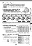
5(R1) 1(P) 3(R2) 5(R1) 1(P) 3(R2) 5(R1) 1(P) 3(R2) 4(A) 2(B) 4(A) 2(B) 4(A) 2(B) IP67 enclosure compatible kit (Serial transmission) S 25 pins kit (D-sub connector) F 26 pins, 20 pins kit (Flat ribbon cable) P IP67 enclosure compatible kit (Terminal block box) T IP67 enclosure compatible 25-core cable kit (Lead wire) L IP67 enclosure compatible 26 pins kit (Circular connector) M Top entry Side entry 1 2 3 4 5 6 7 8 9 10 5 6 7 8 9 10 6 7 8 9 10 5 6 7 8 9 10 5 6 7 8 9 10 5 6 7 8 9 10 5 6 7 8 9 10 5 6 7 8 9 10 5 6 7 8 9 10 19 20 19 20 19 20 19 20 19 20 19 20 19 20 19 20 6 A 4 A 3 A 1 A 5 B 2 B Output COM. 1 2 3 4 1 2 3 4 1 2 3 4 1 2 3 4 1 2 3 4 1 2 3 4 1 2 3 4 1 2 3 4 5 R1 A P B R2 Series VQC1000 VQC2000 Manifold pitch (mm) 10.5 16 Flow-rate characteristics Note) Metal seal Rubber seal Applicable cylinder bore size (mm) Up to o50 Up to o80 The connector entry direction can be changed from the top to the side by simply pressing the manual release button. It is not necessary to use the manual release button when switching from the side to the top. C [dm3/(s・bar)] b Cv C [dm3/(s・bar)] b Cv 0.72 2.6 0.25 0.15 0.18 0.60 1.0 3.2 0.30 0.30 0.25 0.80 Note) Flow-rate characteristics: 2-position single, 4/2 → 5/3 (A/B → R1/R2) A wide variety of prepackaged wiring configurations Compact and high flow Connector entry direction can be changed with a single push. (F/P kit) Connector type manifold 傱 The use of multi-pin connectors to replace wiring inside manifold blocks provides flexibility when adding stations or changing manifold configuration. 傱 All kits use multi-pin connectors, so switching from the F kit (D-sub connector) to the S kit (serial transmission) can be done simply by changing the kit section. 傱 Two 3-port valves built into one body 傱 The 3-port valves on the A and B sides can operate independently. 傱 When used as 3-port valves, only half the number of stations is required. 傱 Can also be used as a 4-position, 5-port type valve. 傱 Our six standard wiring packages bring a world of ease to wiring and maintenance work, while the protective enclosures of four of them conform to IP67 standards. 傱 The S kit is compatible with a combined I/O unit. (Not applicable to Gateway unit) Connector wiring diagram (Mixed wiring) Station 1 Double wiring Station 2 Single wiring Station 3 Double wiring Station 4 Single wiring Dual 3-port valves, 4 positions VQC1000/2000 (Rubber seal only) Exhaust center : VQC1A01 : VQC2A01 Pressure center : VQC1B01 : VQC2B01 VQC1A01 VQC2A01 VQC1B01 VQC2B01 VQC1C01 VQC2C01 Model A side B side Symbol (Refer to the connector wiring diagram.) Printed circuit board patterns between connectors are shifted at every station. This allows for viable connections to take place without necessarily specifying whether the manifold station is double, single, or mixed wiring. N.C. valve N.C. valve N.O. valve N.O. valve N.C. valve N.O. valve 1155 SY SJ SY SV SYJ SZ VF VP4 S0700 VQ VQ4 VQ5 VQC VQC4 VQZ SQ VFS VFR VQ7