1-p1153-1215-vqc1000_en 43 / 64
10秒後にBOOKのページに移動します
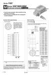
!5 q !4 !3 @4 !2@3 !1 @2 !0 o i @1 @6 @5 !6 !7 w e !8 r !9 y t @0 u 015 M 1 2 3 4 5 6 7 8 9 10 11 12 13 14 15 16 17 18 19 20 21 22 23 24 25 26 Station 1 Station 2 Station 3 Station 4 Station 5 Station 6 Station 7 Station 8 Station 9 Station 10 Station 11 Station 12 Series VQC1000/2000 Kit (Circular connector) IP67 compliant . Use of circular connectors helps streamline wiring procedure to save labor. . IP67 enclosure is available with use of waterproof circular connectors. AXT100-MC26- 015 030 050 Electrical Wiring Specifications Circular connector Double wiring (connected to SOL.A and SOL.B) is used for the internal wiring of each station, regardless of valve and option types. Mixed single and double wiring are available as an option. Refer to the below special wiring specifications (option). Cable Assembly Type 26P circular connector cable assembly can be ordered with manifolds. Refer to “How to Order Manifold.” Note) When using the negative COM specification, use valves for negative COM. Mixed single and double wiring are available as an option. The maximum number of manifold stations is determined by the number of solenoids. Count one point for a single solenoid type and two points for a double solenoid type. The total number of solenoids (points) must not exceed 24. Special Wiring Specifications (Option) 1.5 m 3 m 5 m Circular connector cable assembly Cable length (L) . Cannot be used for transfer wiring. . Lengths other than the above is also available. Please contact SMC for details. 26P AXT100-MC26-015 AXT100-MC26-030 AXT100-MC26-050 Assembly part no. o30 L 60 Plug (.) (.) (.) (.) (.) (.) (.) (.) (.) (.) (.) (.) (.) (.) (.) (.) (.) (.) (.) (.) (.) (.) (.) (.) (+) (+) (+) (+) (+) (+) (+) (+) (+) (+) (+) (+) (+) (+) (+) (+) (+) (+) (+) (+) (+) (+) (+) (+) (+) (+) (.) (.) Positive COM spec. Negative COM spec. Note) Terminal Polarity no. Seal (Length) Cable 0.3 mm2 x 25 cores O.D. o1.4 Approx. o10 Lead wire colors for circular connector cable assembly terminal numbers Terminal no. Lead wire color Dot marking 1 2 3 4 5 6 7 8 9 10 11 12 13 14 15 16 17 18 19 20 21 22 23 24 25 26 Black Brown Red Orange Yellow Pink Blue Purple Gray White White Yellow Orange Yellow Pink Blue Purple Gray Orange Red Brown Pink Gray Black White White None None None None None None None White Black Black Red Red Red Black Black White None None Black White White Red Red White None None Electrical characteristics Item Conductor resistance Ω/km, 20°C Voltage limit V, 1 minute, AC Insulation resistance MΩ/km, 20°C Property 65 or less 1000 5 or more Note) The minimum bending radius of the circular connector cable is 20 mm. 26 25 24 23 22 20 21 19 18 17 16 15 14 13 12 11 10 7 8 9 6 5 4 3 2 1 Terminal no. M27 female thread SOL.A SOL.B SOL.A SOL.B SOL.B SOL.A SOL.B SOL.A SOL.B SOL.A SOL.B SOL.A SOL.B SOL.A SOL.B SOL.A SOL.B SOL.A SOL.B SOL.A SOL.B SOL.A SOL.B SOL.A COM. COM. 1194 Series VQC A