1-p1153-1215-vqc1000_en 37 / 64
10秒後にBOOKのページに移動します
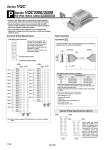
P AXT100-FC 2 0 - 26 123 26 24 22 20 18 16 14 12 10 8 6 4 2 25 23 21 19 17 15 13 11 9 7 5 3 1 1 2 3 4 5 6 7 8 9 10 11 12 13 14 15 16 17 18 19 20 21 22 23 24 25 26 1 2 3 4 5 6 7 8 9 10 11 12 13 14 15 16 17 18 19 20 20 18 16 14 12 10 8 6 4 2 19 17 15 13 11 9 7 5 3 1 IP40 compliant Series VQC1000/2000 Kit (Flat ribbon cable) . Using our flat ribbon cable for electrical connections greatly reduces labor, while it also minimizes wiring and saves space. . We use flat ribbon cables whose connectors (26P and 20P) conform to MIL standards, and are therefore widely compatible with many standard commercial models. . Top or side entry for the connector can be changed freely, allowing for changes even after mounting, to meet any changing needs for space. Electrical Wiring Specifications Flat ribbon cable connector Connector terminal number Triangle mark indicator position Double wiring (connected to SOL. A and SOL. B) is adopted for the internal wiring of each station, regardless of valve and option types. Mixed single and double wiring are available as an option. Refer to the below special wiring specifications (option). Station 1 Station 2 Station 3 Station 4 Station 5 Station 6 Station 7 Station 8 Station 9 Station 10 Station 11 Station 12 (.) (.) (.) (.) (.) (.) (.) (.) (.) (.) (.) (.) (.) (.) (.) (.) (.) (.) (.) (.) (.) (.) (.) (.) (+) (+) Positive COM spec. (+) (+) (+) (+) (+) (+) (+) (+) (+) (+) (+) (+) (+) (+) (+) (+) (+) (+) (+) (+) (+) (+) (+) (+) (.) (.) Negative COM spec. Note) Note) Station 1 Station 2 Station 3 Station 4 Station 5 Station 6 Station 7 Station 8 Station 9 (.) (.) (.) (.) (.) (.) (.) (.) (.) (.) (.) (.) (.) (.) (.) (.) (.) (.) (+) (+) (+) (+) (+) (+) (+) (+) (+) (+) (+) (+) (+) (+) (+) (+) (+) (+) (+) (+) (.) (.) Positive COM spec. Negative COM spec. Terminal no. Terminal Polarity no. Polarity <26P> <20P> Note) When using the negative COM specification, use valves for negative COM. COM COM COM COM Mixed single and double wiring are available as an option. The maximum number of manifold stations is determined by the number of solenoids. Count one point for a single solenoid type and two points for a double solenoid type. The total number of solenoids (points) must not exceed 24. (26P) (20P) Special Wiring Specifications (Option) 1.5 m 3 m 5 m 26P AXT100-FC26-1 AXT100-FC26-2 AXT100-FC26-3 20P AXT100-FC20-1 AXT100-FC20-2 AXT100-FC20-3 Flat ribbon cable connector assembly Cable length (L) Assembly part no. Connector Manufacturers’ Example . Hirose Electric Co., Ltd. . . Fujitsu, Ltd. . Japan Aviation Electronics Industry, Ltd. . J.S.T. Mfg. Co., Ltd. . Oki Electric Cable Co., Ltd. . When using a standard commercial connector, use a type 26P connector conforming to MIL-C-83503 or a type 20P with strain relief. . Cannot be used for transfer wiring. . Lengths other than the above is also available. Please contact SMC for details. 26 24 22 20 18 16 14 12 10 8 6 4 2 25 23 21 19 17 15 13 11 9 7 5 3 1 6 (15.6) L 28AWG 30 (20P) 37.5 (26P) 26 2 25 1 Cable Assembly Terminal no. Red Type 26P flat ribbon cable connector assembly can be ordered with manifolds. Refer to “How to Order Manifold.” Sumitomo 3M Limited SOL.A SOL.B SOL.A SOL.B SOL.B SOL.A SOL.B SOL.A SOL.B SOL.A SOL.B SOL.A SOL.B SOL.A SOL.B SOL.A SOL.B SOL.A SOL.B SOL.A SOL.B SOL.A SOL.B SOL.A COM. COM. SOL.B SOL.A SOL.B SOL.A SOL.B SOL.A SOL.B SOL.A SOL.B SOL.A SOL.B SOL.A SOL.B SOL.A SOL.B SOL.A SOL.B SOL.A COM. COM. 1188 Series VQC