1-p1153-1215-vqc1000_en 12 / 64
10秒後にBOOKのページに移動します
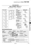
N.C. N.C. N.O. N.O. N.C. N.O. B A B A B A A B A B A B A B A B A A How to Order Valves Yes None (Non-polar) Nil E Note1, 2) Standard (0.4 W) High-speed response type (0.95 W) High-pressure type (1.0 MPa, 0.95 W) Negative common External pilot B K Note 2) N Note 3) R Note 4) Nil VQC1 1 0 0 Series VQC1000 5 1 1 4-position dual 3-port valve (A) 4-position dual 3-port valve (B) 4-position dual 3-port valve (C) A B C Note) Note) Note) 2 3 4 5 Note) Rubber seal only Nil: Non-locking push type (Tool required) B: Locking type (Tool required) C: Locking type (Manual) D: Slide locking type (Manual) Note 1) When two or more symbols are specified, indicate them alphabetically. However, combination of “B” and “K” is not possible. Note 2) Metal seal only Note 3) When “-COM.” is specified for the SI unit, select and mount the valve of negative common. Note 4) Dual 3-port is not applicable. Note 1) Not applicable to the S kit. Note 2) A combination of “Function N (Negative common)” and “E” is unavailable. Since “E” has no polarity, it can also be used as a negative common. Selection of “Function N” is not required. Metal seal Rubber seal 0 1 How to Order Manifold Assembly Example Manifold Power supply with M12 connector For the I/O unit part number mounted, refer to catalog CAT.E02-24. . Digital unit . Analog unit 2-position single 2-position double (Metal) 2-position double (Rubber) 3-position closed center 3-position exhaust center 3-position pressure center Serial transmission kit VV5QC11-08C6SD6Q2N2 ・・・・ 1 set Manifold base part number . VQC1100N-51 ・・・・・・・・・・・・・・・・・・ 2 sets Valve part number (Stations 1 to 2) . VQC1200N-51 ・・・・・・・・・・・・・・・・・・ 5 sets Valve part number (Stations 3 to 7) . VVQ1000-10A-1 ・・・・・・・・・・・・・・・ 1 set Blanking plate number (Station 8) . EX600-DXPD ・・・・・・・・・・・・・・・・・・・ 1 set I/O unit part number (Station 1) . EX600-DYPB ・・・・・・・・・・・・・・・・・・・ 1 set I/O unit part number (Station 2) The asterisk denotes the symbol for assembly. Prefix it to the part nos. of the solenoid valve, etc. Note) Do not enter the SI unit part number and the end plate part number together. Enter in order starting from the first station on the D-side. When entry of part numbers becomes complicated, indicate with the manifold specification sheet. Enter in order starting from the first station on the D-side. When entry of part numbers becomes complicated, indicate with the manifold specification sheet. Digital input unit EX600-DXPD End plate Note) EX600-ED2 D side SI unit EX600-SDN1 Digital output unit EX600-DYPB 2-position single VQC1100N-51 2-position double VQC1200N-51 Blanking plate VVQ1000-10A-1 U side 1 2 3 4 5 6 7 8 Valve stations I/O unit stations 1 2 Note) 24 VDC 12 VDC 5 Note) 6 Note) Only 24 VDC is available with the S kit. Coil voltage Function Light/surge voltage suppressor Type of actuation Seal Manual override Base Mounted Plug-in Unit Series VQC1000 (R1)5 1 (P) 3(R2) (A)4 2(B) (R1)5 1 (P) 3(R2) (A)4 2(B) (R1)5 1 (P) 3(R2) (A)4 2(B) (R1)5 1 (P) 3(R2) (A)4 2(B) (R1)5 1 (P) 3(R2) (A)4 2(B) (R1)5 1 (P) 3(R2) (A)4 2(B) 5(R1) 1(P) 3(R2) 5(R1) 1(P) 3(R2) 5(R1) 1(P) 3(R2) 4(A) 2(B) 4(A) 2(B) 4(A) 2(B) 1163 SY SJ SY SV SYJ SZ VF VP4 S0700 VQ VQ4 VQ5 VQC VQC4 VQZ SQ VFS VFR VQ7 A