1-p1065-1108-vq4000_en 9 / 45
10秒後にBOOKのページに移動します
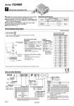
F Kit (D-sub connector kit) Manifold Specifications Series VQ4000 Porting specifications 4(A), 2(B) Port size 1(P), 5(R1), 3(R2) Rc 1/2 C 8, 10, 12 Rc 1/4, 3/8 Rc 1/4 VV5Q Manifold Option 08 Stations C8 F U Cylinder port C6 C8 C10 C12 02 03 B CM 1 Plug-in unit D-sub Connector Cable Assembly Terminal No. Terminal no. 1 2 3 4 5 6 7 8 9 10 11 12 13 14 15 16 17 18 19 20 21 22 23 24 25 D-sub Connector Cable Assembly Cable length (L) Assembly part no. Note 1.5 m 3 m 5 m AXT100-DS25-015 AXT100-DS25-030 AXT100-DS25-050 Item Characteristics Conductor resistance Ω/km, 20°C Voltage limit VAC, 1 min. Insulation resistance MΩkm, 20°C 65 or less 1000 5 or less 1 1 Series 4 VQ4000 4 Connector entry direction D U Cable (Length) 0 1 2 3 16 44 L 8 14 25 1 13 47.04 55 2 x M2.6 x 0.45 D-Sub Connector Kit (25 pins) How to Order Manifold Simplification and labor savings for wiring work can be achieved by using a D-sub connector for the electrical connection. Using connector for flat ribbon cable (25P) conforming to MIL standard permits the use of connectors put on the market and gives a wide interchangeability. Connector entry can be selected on either the U side or the D side according to the mounting orientation. Maximum stations are 18. 4(A), 2(B) port location Applicable stations Max. 18 stations AXT100-DS25- 015 030 050 D-sub connector cable assemblies can be ordered by with manifolds. Refer to How to Order Manifold. Multi-core vinyl cable 0.3 mm2 x 25C .o10 Socket side Terminal no. Cable 25 cores x 24AWG . For other commercial connectors, use a 25 pins type with female connector conforming to MIL-C-24308. . Cannot be used for transfer wiring. Connector manufacturers’ example . Fujitsu, Ltd. . Japan Aviation Electronics Industry, Ltd. . J.S.T. Mfg. Co., Ltd. . Hirose Electric Co., Ltd. Electric Characteristics Note) The minimum bending radius for D-sub connector cables is 20 mm. Cable assembly Lead wire color Black Brown Red Orange Yellow Pink Blue Purple Gray White White Yellow Orange Yellow Pink Blue Purple Gray Orange Red Brown Pink Gray Black White None None None None None None None White Black Black Red Red Red Black Black White None None Black White White Red Red White None Dot marking 01 1 station 18 18 stations ... ... With One-touch fitting for o6 With One-touch fitting for o8 With One-touch fitting for o10 With One-touch fitting for o12 Rc 1/4 Rc 3/8 Bottom ported Rc 1/4 Mixed Note) As a semi-standard specification, the maximum number of stations can be increased by special wiring specifications. For details, refer to page 1073. Without cable Cable length 1.5 m Cable length 3 m Cable length 5 m D side entry U side entry Symbol Nil CD (2) CU (2) K (3) SB SD (2) SU (2) Option None Exhaust cleaner: For D side mounting Exhaust cleaner: For U side mounting Special wiring specifications (Except double wiring) Direct exhaust with silencer box: Exhaust from both sides Direct exhaust with silencer box: D side exhaust Direct exhaust with silencer box: U side exhaust Note 1) When two or more symbols are specified, indicate them alphabetically. Example) -CDK Note 2) Combination of [C ] and [S ] is not possible. Note 3) Specify the wiring specifications on the manifold specification sheet. Note 4) Refer to pages 1098 to 1101 for with control unit. UD UD CE compliant Nil . Q CE compliant Side Bottom Note) Lengths other than the above are also available. Please contact SMC for details. Series VQ4000 [Option] Nil F T Thread type Rc G NPT/NPTF 1072