1-p1065-1108-vq4000_enЃ@Ѓ@Ѓ@45 / 45
10•bЊг‚ЙBOOK‚МѓyЃ[ѓW‚Й€Ъ“®‚µ‚Ь‚·
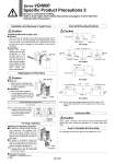
Varistor Varistor Varistor A B р‘ Removal 1) Remove the mounting screw that holds the pilot valve using a small screwdriver. р‘ Installation 1) After confirming the gasket is correctly placed under the valve, securely tighten the bolts with the proper torque shown in the table below. Caution Caution Caution Caution Installation/Removal of light cover р‘ Removal Open the cover by inserting a small flat head screwdriver into the slot on the side of the pilot assembly (see drawing below), lift the cover out about 1 mm and then pull off. If it is pulled off at an angle, the pilot valve may be damaged or the protective O-ring may be scratched. р‘ Installation Place the cover straight over the pilot assenmbly so that the pilot valve is not touched,and push it until the cover hook locks without twisting the protective O-ring. (When pushed in, the hook opens and locks automatically.) O-ring Light cover Replacement of Pilot Valve Light assembly Mounting screw B side A side Proper tightening torque (NЃEm) 0.1 to 0.13 For Plug Lead Type Attaching and detaching connectors р‘To attach a connector, hold the lever and connector unit between your fingers and insert straight onto the pins of the solenoid valve so that the leverЃfs pawl is pushed into the groove and locks. р‘To detach a connector, remove the pawl from the groove by pushing the lever downward with your thumb, and pull the connector straight out. Note) Do not pull on the lead wires with excessive force. This can cause faulty and/or broken contacts. Connector Lever Internal Wiring Specifications DC: Single A side . (+) B side . (+) DC: Double AC: Single A side B side AC: Double Enclosure IP65 Wires, cables, connectors, etc. used for models conforming to IP65 should also have enclosures equivalent to or stricter rating than IP65. How to Calculate the Flow Rate For obtaining the flow rate, refer to front matters 42 to 45. Mounting indicator Note) The light circuit boards: A side is orange and the B side is green. It must be mounted on the pilot valve in accordance with the mounting indicators. Note) For DC, coil surge voltage generated when OFF is about .60V. Contact SMC separately for further suppression of the coil surge voltage. Installation and Removal of Light Cover Series VQ4000 Specific Product Precautions 2 Be sure to read before handling. Refer to front matter 53 for Safety Instructions and pages 3 to 8 for 3/4/5 Port Solenoid Valve Precautions. COM: +(.) COM: +(.) .(+) +(.) LED: Orange COM.: +(.) LED: Orange Solenoid coil Solenoid coil Solenoid coil Solenoid coil Solenoid coil Solenoid coil A side LED: Orange COM: +(.) B side LED: Green A side LED: Orange B side LED: Green рЋTreadmark Intormation DeviceNet. is a trademark of ODVA. 1108