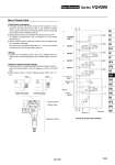
Use of Control Unit VQ410 01 VQ420 01 VQ430 01 VQ44001 VVQ4000 -10A-1 B A 1. Pressure switch (3) is changed to piping on inlet side of release valve (2), remove the pressure switch, reverse the gasket up and down, and fix B mark. 2. When pressure switch is mounted, tightening torque of bolt is 0.8 to 1.2 N・m. 1. The supply pressure (Po) passes through the filter regulator (1) and is adjusted to the prescribed pressure. Next, it goes through the release valve (2) (outlet residual pressure switching function used as normally ON) and is supplied to the manifold base side (P). 2. Supply pressure from Po port is blocked when release valve (2) is OFF. Air supplied to manifold side P port is exhausted to R1 port through release valve (2). 3. Pressure switch is piped at outlet side of release valve (2). (Release valve (2) is operated at energizing.) Also, since there is an internal voltage drop of 4 V, it may not be possible to confirm the OFF and ON states with a tester, etc. 1. Electrical entry of manifold (except L and C kit) is individual wiring. For details, refer to internal wiring figure of each kit. Cable length is 0.6 m for L kit. Gasket Gasket Outlet side piping Inlet side piping Pressure switch Release valve Regulator with filter Stations 1 2 3 4 5 6 n 7 (2) Release valve (ON) (3) Pressure switch (1) Filter regulator (Supply port) Control unit Circuit of control unit manifold Base Mounted Series VQ4000 P1 A B R2 A B A B A B A B P2 P" P1 R1 P R2 Po R1 P 1099 SY SJ SY SV SYJ SZ VF VP4 S0700 VQ VQ4 VQ5 VQC VQC4 VQZ SQ VFS VFR VQ7