1-p1065-1108-vq4000_en 25 / 45
10秒後にBOOKのページに移動します
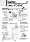
Electrical entry G Lead wire length 0.6 m H Lead wire length 1.5 m VQ 4 Type of actuation Series 1 2 3 4 5 6 Seal 0 1 Manual override 4 VQ4000 5 Function VV5Q Manifold Option 08 Stations C8 Cylinder port C6 C8 C10 C12 02 03 B CM 5 Plug lead unit 5 Series 4 VQ4000 4 W Control unit Kit type C C kit (Connector) C Connector kit Enclosure Light/Surge voltage suppressor Coil voltage 1 2 3 4 5 6 1 0 5 G How to Order Manifold How to Order Valves How to Order Manifold Assembly Base Mounted Plug Lead Unit: C Kit (Connector kit) Series VQ4000 01 1 station 16 16 stations ... ... With One-touch fitting for o6 With One-touch fitting for o8 With One-touch fitting for o10 With One-touch fitting for o12 Rc 1/4 Rc 3/8 Bottom ported Rc 1/4 Mixed Refer to pages 1098 to 1101. Max. 16 stations Symbol Nil CD (2) CU (2) SB SD (2) SU (2) W Option None Exhaust cleaner: For D side mounting Exhaust cleaner: For U side mounting Direct exhaust with silencer box: Exhaust from both sides Direct exhaust with silencer box: D side exhaust Direct exhaust with silencer box: U side exhaust IP65 enclosure UD UD Note 1) When two or more symbols are specified, indicate them alphabetically. Example) -CDW Note 2) Combination of [C ] and [S ] is not available. Refer to page 1107 (Grommet type) for wiring specifications. CE-compliant Nil . Q CE-compliant 2 position single 2 position double 3 position closed center 3 position exhaust center 3 position pressure center 3 position double check Metal seal Rubber seal Nil Y (1) R (2) Standard type (1 W) Low wattage type (0.5 W) External pilot 100 VAC (50/60 Hz) 200 VAC (50/60 Hz) 110 VAC (50/60 Hz) 220 VAC (50/60 Hz) 24 VDC 12 VDC Nil Dusttight W Dusttight/Low jetproof type (IP65) Nil: Non-locking push type (Tool required) B: Locking type (Tool required) Nil E Yes Without light, with surge voltage suppressor Grommet Specify the part numbers for valves and options together beneath the manifold base part number.