1-p1065-1108-vq4000_en 21 / 45
10秒後にBOOKのページに移動します
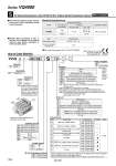
S Kit (Serial transmission unit): EX123/124 (For Output) Serial Transmission System VV5Q Manifold 08 Stations C8 S Cylinder ports C6 C8 C10 C12 02 03 B CM 1 Plug-in unit 1 Series 4 VQ4000 4 V F1 H J1 J2 Q R1 R2 V Symbol Protocol type NKE Corp.: Fieldbus System NKE Corp.: Fieldbus H System DeviceNet OMRON Corp.: CompoBus/S System (16 output points) OMRON Corp.: CompoBus/S System (8 output points) CC-Link SI unit part no. Page P.1165 D side: EX123D-SUH1 U side: EX123U-SUH1 D side: EX123D-SSL1 U side: EX123U-SSL1 D side: EX123D-SSL2 U side: EX123U-SSL2 D side: EX124D-SDN1 U side: EX124U-SDN1 D side: EX124D-SCS1 U side: EX124U-SCS1 D side: EX124D-SCS2 U side: EX124U-SCS2 D side: EX124D-SMJ1 U side: EX124U-SMJ1 D side: EX123D-SUW1 U side: EX123U-SUW1 CE compliant . . . . How to Order Manifold The serial transmission system reduces wiring work, while minimizing wiring and saving space. Manifold Specifications Series VQ4000 Porting specifications 1(P) ,5(R1), 3(R2) 4(A), 2(B) Rc 1/2 C8, 10, 12 Rc 1/4, 3/8 Rc 1/4 Double wiring (connected to SOL. A and SOL. B) is adopted for the internal wiring of each station, regardless of valve and option types. Specifications 0.1A Drip proof plug assembly (for G 1/2): AXT100-B04A IP65 compliant 4(A), 2(B) port port location Port size Side Bottom Applicable stations Max. 18 stations Item Current consumption (Internal unit) External power supply 24 VDC +10%, .5% 03 3 stations 18 18 stations ... ... Stations are counted starting from the first station on the D side. With One-touch fitting for o6 With One-touch fitting for o8 With One-touch fitting for o10 With One-touch fitting for o12 Rc 1/4 Rc 3/8 Bottom ported Rc 1/4 Mixed Note) 2 stations are used for mounfing SI unit. The number of stations is the number of manifold valves plus 2 stations for SI unit. For 11 stafions or more, specify the wiring specifications by means of the manifold specification sheet. SI Unit Part No. Option Symbol Nil CD (2) CU (2) K (3) SD (2) SU (2) W (2) Option None Exhaust cleaner: D side mounting Exhaust cleaner for Rc 1: U side exhaust Special wiring specifications (Except double wiring) Direct exhaust with silencer box: D side exhaust Direct exhaust with silencer box: U side exhaust IP65 enclosure SI unit 0 F1 H J1 J2 Q R1 R2 V Without SI unit NKE Corp.: Fieldbus System NKE Corp.: Fieldbus H System Panasonic Industrial Devices SUNX Co., Ltd.: S-LINK (16 output points) Panasonic Industrial Devices SUNX Co., Ltd.: S-LINK (8 output points) DeviceNet OMRON Corp.: CompoBus/S System (16 output points) OMRON Corp.: CompoBus/S System (8 output points) CC-Link CE-compliant . CE-compliant Note) Refer to “SI Unit Part No.” when ordering the CEcompliant SI unit. Q Nil Note 1) When two or more symbols are specified, indicate them alphabetically. Example) -CDK Note 2) Combination of [CD] and [SD] is not possible. Note 3) Specify the wiring specifications in the manifold specification sheet. Note 4) Refer to pages 1098 to 1101 for with control unit.consumption of AC type. Note 5) The release valve and the pressure switch on the manifold with control unit are connected to another power supply. Cable length is 0.6 m for L kit. 1 2 3 ・・・・・・・・・・・・Stations G 1/2 D side U side SI unit mounting position Nil D U side mounting D side mounting Series VQ4000 [Option] Note) Refer to “SI Unit Part No.” when ordering the CE-compliant SI unit. Refer to page 2055 and the Operation Manual for the details of EX123/124 Integratedtype (For Output) Serial Transmission System. Please download the Operation Manual via our website, http://www.smcworld.com Nil F T Thread type Rc G NPT/NPTF Panasonic Industrial Devices SUNX Co., Ltd.: S-LINK (16 output points) Panasonic Industrial Devices SUNX Co., Ltd.: S-LINK (8 output points) 1084