1-p1065-1108-vq4000_en 14 / 45
10秒後にBOOKのページに移動します
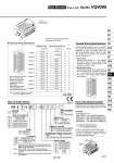
VQ 4 Type of actuation Series 1 2 3 4 5 6 Seal 0 1 Coil voltage Manual override Ligh/Surge voltage suppressor 4 VQ4000 Terminal no. Polarity Special Wiring Specifications 0 1 2 3 4 5 6 Function Enclosure W Terminal no. 2 x G 3/4 Electrical entry Standard wiring Wiring with control unit 1 0 5 1A 2A 3A 4A 5A 6A 7A 8A 9A 10A COM 1B 2B 3B 4B 5B 6B 7B 8B 9B 10B 1B 1A 2B 2A 3B 3A 4B 4A 5B 5A 6B 6A 7B 7A 8B 8A 9B 9A 10B 10A COM 1A 2A 3A 4A 5A 6A 7A 8A 9A 10A COM 1B 2B 3B 4B 5B 6B 7B 8B 9B 10B 1B 1A 2B 2A 3B 3A 4B 4A 5B 5A 6B 6A 7B 7A 8B 8A 9B 9A 10B 10A COM How to Order Valves How to Order Manifold Assembly Stations are counted starting from the first station on the D side. Electrical wiring specifications Double wiring (connected to SOL. A and SOL. B) is adopted for the internal wiring of each station, regardless of valve and option types. Mixed single and double wiring is available as a semi-standard specification. Note) There is no polarity. It can also be used as a negative common. 1 station 2 stations 3 stations 4 stations 5 stations 6 stations 7 stations 8 stations 9 stations 10 stations Release valve Pressure switch (.) (+) (+) (.) (.) (+) (+) (.) (.) (+) (.) (+) (.) (+) (.) (+) (.) (+) (.) (+) (.) (+) (.) (+) (.) (+) (.) (+) (.) (+) (.) (+) (.) (+) (.) (+) (.) (+) (.) (+) (+) (.) Positive common Negative common Double wiring (connected to SOL. A and SOL. B) is used for the internal wiring of each station regardless of valve and option types. The optional specification permits mixture of single and double wiring. However, the maximum number of stations is 16. 1. How to Order Indicate option symbol “-K” in the manifold part number and be sure to specify station positions for single or double wiring on the manifold specification sheet. 2. Wiring specifications Connections begin with the A side solenoid of the first station being connected to terminal no. 1, and continue in the order indicated by the arrows in the drawing without skipping any terminals. 2 position single 2 position double 3 position closed center 3 position exhaust center 3 position pressure center 3 position double check Metal seal Rubber seal Nil Y (1) R (2) Standard type (1 W) Low wattage type (0.5 W) External pilot Nil Dust tight Dust tight/Low jetproof type (IP65) Nil B Non-locking push type (Tool required) Locking type (Tool required) Nil E Yes Without light, with surge voltage suppressor 100 VAC (50/60 Hz) 200 VAC (50/60 Hz) 110 VAC (50/60 Hz) 220 VAC (50/60 Hz) 24 VDC 12 VDC Specify the part numbers for valves and options together beneath the manifold base part number.