1-p0987-1063-vq1000_en 69 / 78
10秒後にBOOKのページに移動します
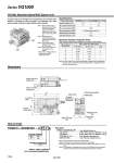
Dimensions How to Order VV5Q11 05C6FU0 J Vacuum switch Nil P None With VQ1000: Manifold Option/With Ejector Unit An ejector unit can be mounted on the manifold base for a solenoid valve. Instead of mounting the valve and ejector unit separately, this option reduces piping, wiring and creates additional space savings. Specifications Maximum Number of Ejector Units Ejector valve model Nozzle diameter (mm) Max. suction flow rate N (NL/min) Max. vacuum pressure (mmHg) Max. operating pressure (MPa) Standard supply pressure (MPa) Operating temperature (°C) VVQ1000-J-1-A 0.7 11 VVQ1000-J-1-B 1.0 20 .630 0.7 (High-pressure type 0.8) 0.5 5 to 50 Max. number of ejector units 1 2 3 4 5 F, P, T kit 11 (20) 10 (16) 9 (12) 8 (8) 4 (4) 7 (14) 6 (12) 5 (10) 4 (8) 3 (4) 7 6 5 S, G, J kit Max. number of mounted valves L kit P 1 S 1 to 5 Number of ejectors Others, option symbols: to be indicated alphabetically. Example) VV5Q11-05C6FU0-JP1 .VQ1100-51 .VQ1200-51 .VVQ1000-J1-51-A .ZSE1-00-15CL 1 set.Manifold part no. 2 sets.Valve part no. (Stations 1 to 2) 2 sets.Valve part no. (Stations 3 to 4) 1 set.Ejector valve part no. 1 set.Vacuum switch part no. (Max. number of ejector units is subject to the number of valve stations.) Note 1) SUP and EXH ports on the ejector unit manifold base are arranged on D-side alone. The end plate on the U-side is the same as that used in the L kit. Note 2) Individual piping is provided for the supply and exhaust ports of the ejector unit. Note 3) The manifold with an ejector unit is mounted from the U-side. Note 4) One vacuum ejector unit corresponds to one station. . Specify the mounting station by means of the manifold specification sheet. Note 1) Count one ejector unit as one manifold station. Note 2) The ejector unit is mounted next to the U-side end plate. Note 3) The U-side end plate is used exclusively for ejector units. (Without P and R port) Note 4) The dimension of manifold with an ejector unit is different from the standard dimension. See the formula for calculating the dimensions for each kit. Note) The max. number of mounted valves applies to double wiring. Parenthesized numbers apply to single wiring. Please contact SMC for conditions other than the above or mixed wiring. ...... ......................... ......................... ............... .................... 432 1 4321 4 3 2 1 A B HYS SET R V A B A B D side U side 63 94 86 37.2 Vacuum release valve Air supply valve Vacuum pressure switch Ejector valve Restrictor (Release flow adjustment) Manual override for release valve Manual override for supply valve Indicator light Ejector SUP port (C6) Ejector EXH port (C8) Vacuum port (C6) 1054 Series VQ1000