1-p0987-1063-vq1000_enĀ@Ā@Ā@47 / 78
10ēbĆ„ā…BOOKāŐÉyĀ[ÉWā…ąŕďģāĶā‹ā∑
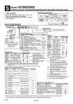
Note 1) When two or more symbols are specified, indicate them alphabetically. Example) -BRS. Note 2) Models with a suffix Āg-BĀh have check valves for prevention of back pressure at all manifold stations. When a back pressure check valve is desired, and is to be installed only in certain manifold stations, specify the mounting position by means of the manifold specification sheet. Note 3) The number of stations that may be displayed is longer than the manifold number of stations. Note 4) Specify the mounting position by means of the manifold specification sheet. Note 5) Refer to page 1054 for details on with vacuum ejector unit. A combination of ĀgJĀh and ĀgNĀh is not available. Note 6) Specify the wiring specifications by means of the manifold specification sheet. Note 7) Indicate ĀgRĀh for the valve with external pilot. Note 8) Refer to ĀgDimensionsĀh on page 1035 for SI unit and valve, in case of W (Dust-tight, Water-jet-proof). Note 9) G1, G2, or G3 cannot be combined with N. Refer to pages 2051 and 2055 and the Operation Manual for the details of EX120/123/124 Integrated-type (for Output) Serial Transmission System. Please download the Operation Manual via our website, http://www.smcworld.com F1 H J1 J2 Q R1 R2 V ZB ZBN Symbol Protocol VQ1000 VQ2000 1 2 Option Symbol VQ1000 VQ2000 C3 Note 1) C4 Note 1) C6 Note 1) C8 Note 1) M5 CM Note 2) Note 3) MM Note 4) Cylinder port Manifold 1 Plug-in unit SI unit specifications Series VV5Q 1 1 08 C6 S V 2 stations 16 stations 02 16 Note) Stations Series VQ1000/2000 Kit (Serial transmission): For EX120/123/124 Integrated-type (For Output) Serial Transmission System S Symbol Option VQ1000 VQ2000 Nil B Note 2) D Dū≠ Note 3) G1 G2 G3 Jū≠ Note 5) N R Note 7) S W Note 8) None With back pressure check valve DIN rail mounting DIN rail mounting (ū≠: Stations 02 to 24) 1 set of regulator unit 2 sets of regulator unit 3 sets of regulator unit With ejector unit With name plate With external pilot Direct EXH outlet with built-in silencer K Note 6) Special wiring specifications (Except double wiring) Enclosure: Dust-tight, Water-jet-proof (IP65) Port size With o3.2 One-touch fitting With o4 One-touch fitting With o6 One-touch fitting With o8 One-touch fitting M5 thread Mixed sizes and with port plug Mixed size for different types of piping, option installed 0 F1 H J1 J2 Q R1 R2 V ZB Note) ZBN Note) Without SI unit NKE Corp.: Fieldbus System NKE Corp.: Fieldbus H System Panasonic Industrial Devices SUNX Co., Ltd.: S-LINK (16 outputs) Panasonic Industrial Devices SUNX Co., Ltd.: S-LINK (8 outputs) DeviceNet. System OMRON Corp.: CompoBus/S (16 outputs) OMRON Corp.: CompoBus/S (8 outputs) CC-LINK CompoNet. (Positive common) CompoNet. (Negative common) NKE Corp.: Fieldbus System NKE Corp.: Fieldbus H System Panasonic Industrial Devices SUNX Co., Ltd.: S-LINK (16 outputs) Panasonic Industrial Devices SUNX Co., Ltd.: S-LINK (8 outputs) DeviceNet. System OMRON Corp.: CompoBus/S (16 outputs) OMRON Corp.: CompoBus/S (8 outputs) CC-LINK NKE Corp.: Fieldbus System NKE Corp.: Fieldbus H System Panasonic Industrial Devices SUNX Co., Ltd.: S-LINK (16 outputs) Panasonic Industrial Devices SUNX Co., Ltd.: S-LINK (8 outputs) DeviceNet. OMRON Corp.: CompoBus/S (16 outputs) OMRON Corp.: CompoBus/S (8 outputs) CC-LINK CompoNet. (Positive common) CompoNet. (Negative common) EX123D-SUW1 EX123D-SUH1 EX123D-SSL1 EX123D-SSL2 EX124D-SDN1 EX124D-SCS1 EX124D-SCS2 EX124D-SMJ1 Standard: EX120-SUW1 Standard: EX120-SUH1 Standard: EX120-SSL1 Standard: EX120-SSL2 Standard: EX120-SDN1 Dust-protected: No part no. Standard: EX120-SCS1 Standard: EX120-SCS2 Standard: EX120-SMJ1 Standard: EX120-SCM1 Dust-protected: No part no. Standard: EX120-SCM3 Dust-protected: No part no. SI Unit Part No. (Without option W) SI Unit Part No. (With option W) How to Order Manifold Note 1) Refer to page 1041 for details. Note 2) Max. 16 stations. (Specify a model with 9 to 16 stations by means of the manifold specification sheet.) Protocol Max. 8 stations Max. 8 stations Max.16 stations Max.16 stations Max.16 stations Symbol Stations F1 H J1 J2 Q R1 R2 V Protocol SI unit part no. SI unit part no. CE-compliant CE-compliant Symbol Manifold Specifications Applicable stations Piping Port size direction Side Side Piping specifications Max. 16 stations Max. 16 stations C3, C4, C6, M5 C4, C6, C8 C8 C10 1(P), 3(R) 4(A), 2(B) Series VQ1000 VQ2000 Note 1) Insert ĀgLĀh (Top ported) or ĀgBĀh (Bottom ported) for elbow type. Example) B6 (Bottom ported elbow with o6 One-touch fitting) Note 2) Indicate as ĀgLMĀh (Including upward, downward piping and mixed) for models with elbow fittings and mixed cylinder port sizes. Note 3) Indicate ĀgMixed sizes and with port plugĀh by means of the manifold specification sheet. Note 4) When selecting the mixed size for different types of piping, dual flow fitting assembly, or double check block (direct mounting), enter ĀgMMĀh and give instructions in the manifold specification sheet. Note 5) Inch-size One-touch fittings are available. Refer to ĀgSemi-standardĀh on page 1042 for details. CE-compliant . CE-compliant Nil Q . Refer to ĀgSI Unit Part No.Āh when ordering the CE-compliant SI unit. IP65 compliant ūĎ The serial transmission system reduces wiring work, while minimizing wiring and saving space. ūĎ Enclosure: Dust-tight, Water-jet-proof (IP65) compatible (Series VQ2000) [Option] . Refer to ĀgSI Unit Part No.Āh when ordering the CE-compliant SI unit. Note 4) Note 10) Note 4) Note 10) Note 4) Note 10) ūó ūó ūó ūó . . ūó ūó ūó ūó ūó ūó ūó ūó ūó ūó ūó ūó ūó ūó ūó . ūó ūó ūó . ūó ūó ūó . ūó ūó ūó . ūó ūó . . . . ūó ūó ūó ūó ūó ūó . . . . ūó ūó ūó ūó Note) Communication connector (for the opposite side) is not provided, order it separately. B 1032