1-p0987-1063-vq1000_en 32 / 78
10秒後にBOOKのページに移動します
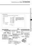
VQ1300-51 VQ1300-51 VQ1300-51 VQ1200-51 VQ1100-51 VQ1100-51 VQ1100-51 3 m Stations U side D side SOL.B SOL.A SOL.B SOL.A 1,2 3,4 5 7 9 11 13 15 17 19 6 8 10 12 14 16 18 20 SOL.B SOL.A SOL.B SOL.A SOL.B SOL.A SOL.B SOL.A SOL.B SOL.A SOL.B SOL.A Type of actuation 2-position single 2-position double 3-position closed center 3-position exhaust center 3-position pressure center 4-position dual port (N.C. +N.C.) 4-position dual port (N.O. +N.O.) 4-position dual port (N.C. +N.O.) 1 2 3 4 5 A B C VQ1000 VQ2000 1 2 Series Metal seal Rubber seal 0 1 Seal VQ 1 1 0 0 5 1 Connector Assembly As the standard electrical wiring specifications, double wiring (connected to SOL. A and SOL. B) is adopted for the internal wiring of each station for 8 stations or less, regardless of valve and option types. Mixed single and double wiring is available as semi-standard. Refer to page 1041 for details. Flat ribbon cable connector Terminal no. Electric circuit diagram (Below wiring is the case of all double solenoid connections.) Station 1 24 VDC Station 2 Station 3 Station 4 Station 5 Connector terminal no. Station 6 Station 7 Station 8 Non-locking push type (Tool required) Locking type (Tool required) Locking type (Manual) Slide locking type (Manual) Manual override Nil B C 24 VDC D Coil voltage 5 Light/Surge voltage suppressor Yes None (Non-polar) Nil E Specify the part numbers for valves and options together beneath the manifold base part number.