1-p0987-1063-vq1000_enü@ü@ü@13 / 78
10ĢbīŃé╔BOOKé╠āyü[āWé╔ł┌ō«éĄé▄éĘ
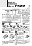
Note 1) 25P Top entry Side entry Top entry Note 1) 26P Side entry Top entry 20P Side entry S kit Without SI unit NKE Corp.: Fieldbus System NKE Corp.: Fieldbus H System Panasonic Industrial Devices SUNX Co., Ltd.: S-LINK (16 outputs) Panasonic Industrial Devices SUNX Co., Ltd.: S-LINK (8 outputs) DeviceNet. OMRON Corp.: CompoBus/S (16 outputs) OMRON Corp.: CompoBus/S (8 outputs) CC-LINK CompoNet.(Positive common) CompoNet.(Negative common) 0 F1 H J1 J2 Q R1 R2 V ZB ZBN Note 2) 2 to 24 stations With cable (1.5 m) With cable (3 m) With cable (5 m) Without cable M kit 0 1 2 3 Option Kit type Symbol Option None 200/220 VAC models (F/L kit only) With back pressure check valve DIN rail mounting With DIN rail bracket (Without DIN rail) DIN rail length specified Special wiring spec. (Except double wiring) With name plate External pilot Direct EXH outlet with built-in silencer Enclosure: Dust-tight, Water-jet-proof (IP65) (T/L/S/M kit only) Nil 2 B Note 2) D D0 DŁ Note 5) K Note 3) N R Note 4) S W Manifold Plug-in unit VV5Q 2 1 08 C6 F U1 01 1 station 1 2 VQ2000 Stations Symbol Port size Symbol Port size C4 C6 C8 CM Note 1) L4 L6 L8 B4 B6 B8 LM Note 1) MM Note 2) Cylinder port Series With o4 One-touch fitting With o6 One-touch fitting With o8 One-touch fitting Mixed sizes and with port plug Top ported elbow with o4 One-touch fitting Top ported elbow with o6 One-touch fitting Top ported elbow with o8 One-touch fitting Bottom ported elbow with o4 One-touch fitting Bottom ported elbow with o6 One-touch fitting Bottom ported elbow with o8 One-touch fitting Elbow port, mixed sizes (Including upward, downward piping and mixed) Mixed size for different types of piping, option installed U0 U1 U2 U3 S0 S1 S2 S3 Note 2) 2 to 24 stations P. 1004 With cable (1.5 m) With cable (3 m) With cable (5 m) Without cable Connector entry direction Top entry Side entry Kit type/Electrical entry/Cable length kit (D-sub connector) F kit F kit F P. 1020 kit (Terminal block box) T kit Dust-tight/Water-jet-proof (IP65) compatible Dust-tight/Water-jet-proof (IP65) compatible O Terminal block box 2 to 20 stations Note 2) T U0 U1 U2 U3 U0 U1 U2 U3 S0 S1 S2 S3 S0 S1 S2 S3 P. 1024 kit (Lead wire) L kit 0 1 2 With cable (0.6 m) With cable (1.5 m) With cable (3 m) 1 to 8 stations L kit (Serial transmission) kit (Circularconnector) S M Note 2) 2 to 24 stations Note 2) 2 to 16 stations P. 1008 P. 1012 With cable (1.5 m) With cable (3 m) With cable (5 m) Without cable With cable (1.5 m) With cable (3 m) With cable (5 m) Without cable Connector entry direction Connector entry direction Top entry Side entry Top entry Side entry kit (Flat ribbon cable) kit (Flat ribbon cable 20P) P kit J kit P kit J kit P J P. 1016 kit (Flat ribbon cable with terminal block) G Note 2) 2 to 16 stations With cable (1.5 m) With cable (3 m) With cable (5 m) Without cable G kit U0 U1 U2 U3 Note 1) Besides the above, F/P kit with different number of pins are available. Refer to page 1040 for details. Note 2) Refer to page 1041 for details. Note 3) Refer to the pages on respective kits for IP65 type. (T/L/S kit) P. 1036 Simple specials are available with SMC Simple Specials System. Refer to the SMC website for details on applicable models. P. 1032 The valve is equipped with an indicator light and surge voltage suppressor, and the voltage is 24 VDC. Dust-tight, Water-jet-proof (IP65) is available. Note 1) When two or more symbols are specified, indicate them alphabetically. Example: -DNR Note 2) Models with a suffix üg-Büh have check valves for prevention of back pressure at all manifold stations. When a back pressure check valve is desired, and is to be installed only in certain manifold stations, specify the mounting position by means of the manifold specification sheet. Note 3) Specify the wiring specifications by means of the manifold specification sheet. (Except L kit) Note 4) Indicate ügRüh for the valve with external pilot. Note 5) Ł: Station. Example: D08: The number of stations that may be displayed is longer than the manifold number of stations. The maximum and minimum number of stations are varied depending on kit. (Refer to the below table.) CE-compliant . CE-compliant Nil Q Note) For CE-compliant models, DC-type only. Note 1) Indicate ügMixed size and with port plugüh by means of the manifold specification sheet. Note 2) When selecting the mixed size for different types of piping, dual flow fitting assembly, or double check block (direct mounting), enter ügMMüh and give instructions in the manifold specification sheet. Note 3) Inch-size One-touch fittings are also available. Refer to page 1042 for details. How to Order Manifold The voltage used for the valve is 24 VDC. Note) For CE-compliant models, DC-type only. Note 2) Max.16 stations Max.16 stations Max.16 stations Max. 8 stations Max. 8 stations Note) Refer to ügSI Unit Part No.üh on page 1032 when ordering the CE-compliant SI unit 998 Plug-in Unit Base Mounted Series VQ2000 [Option] A