1-p0875-0985-s0700_en 87 / 112
10秒後にBOOKのページに移動します
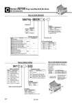
1 2 3 ・・・・・・ Stations D side U side SS0755 08 C4 C How to Order Manifold Plug lead Connector kit Stations Symbol 02 20 Stations 2 stations 20 stations M5 C2 C3 C4 CM N1 N3 NM M3 V2 V3 V4 VM Cylinder port size Symbol Port size Manifold pitch M5 thread With o2 One-touch fitting With o3.2 One-touch fitting With o4 One-touch fitting Mixed sizes and with port plug Note) With o1/8" One-touch fitting With o5/32" One-touch fitting Mixed sizes and with port plug Note) M3 thread With o2 barb fitting With o3.2 barb fitting With o4 barb fitting Mixed sizes and with port plug Note) Metric Inch Metric 8.5 7.5 Symbol Nil R Specifications None External pilot Option Note) Specify “Mixed sizes and with port plug” on the manifold specification sheet. How to Order Valves Type of actuation S07 1 5 5 G Base mounted plug lead Note) For details, refer to page 966. . For manifold optional parts, refer to pages 966 to 968. ・・・ ・・・ P, R port thread type Nil Symbol F N T Manifold pitch 8.5 Rc (PT) G (PF) NPT NPTF 7.5 M5 C Series S0700 Plug Lead Manifold Bar Base kit (Connector) Note) Note) For symbol, refer to page 886. Symbol 1 2 A B C Specifications 2-position single 2-position double 4-position dual 3-port (N.C. + N.O.) 4-position dual 3-port (N.O. + N.O.) [pressure center] 4-position dual 3-port (N.C. + N.C.) [exhaust center] Note) Not compatible with dual 3-port valves. Specifications Standard External pilot Note) Symbol Nil R Function Symbol 5 6 Specifications 24 VDC 12 VDC Voltage Symbol G M MO Specifications Grommet Plug connector, with lead wire (Light/surge voltage suppressor) Plug connector, without lead wire (Light/surge voltage suppressor) Electrical entry 1 set . Manifold base part no. 3 sets . Valve part no. (Stations 1 to 3) 2 sets . Valve part no. (Stations 4 to 5) 2 sets . Valve part no. (Stations 6 to 7) Connector kit SS0755-07C4C ・・・・・・・・ . S0715-5G ・・・・・・・・・・・・・ . S0725-5G ・・・・・・・・・・・・・ . S07A5-5G ・・・・・・・・・・・・・