1-p0875-0985-s0700_en 63 / 112
10秒後にBOOKのページに移動します
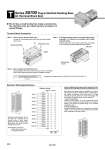
1A 2A 3A 4A 5A 6A 7A 8A 9A 10A COM 1B 2B 3B 4B 5B 6B 7B 8B 9B 10B 1B 1A 2B 2A 3B 3A 4B 4A 5B 5A 6B 6A 7B 7A 8B 8A 9B 9A 10B 10A COM 1A 2A 3A 4A 5A 6A 7A 8A 9A 10A COM 1B 2B 3B 4B 5B 6B 7B 8B 9B 10B 1B 1A 2B 2A 3B 3A 4B 4A 5B 5A 6B 6A 7B 7A 8B 8A 9B 9A 10B 10A COM Polarity (+) (.) (.) (+) (.) (+) (.) (+) (.) (+) (.) (+) (.) (+) (.) (+) (.) (+) (.) (+) (.) (+) (.) (+) (.) (+) (.) (+) (.) (+) (.) (+) (.) (+) (+) (.) (.) (+) (+) (.) (.) (+) Terminal no. Station 10 Station 9 Station 8 Station 7 Station 6 Station 5 Station 4 Station 3 Station 2 Station 1 COM 10B 10A 9B 9A 8B 8A 7B 7A 6B 6A 5B 5A 4B 4A 3B 3A 2B 2A 1B 1A SOL.B SOL.A SOL.B SOL.A SOL.B SOL.A SOL.B SOL.A SOL.B SOL.A SOL.B SOL.A SOL.B SOL.A SOL.B SOL.A SOL.B SOL.A SOL.B SOL.A T Series S0700 Plug-in Manifold Stacking Base kit (Terminal Block Box) This kit has a small terminal box inside a junction box. The electrical entry port (G3/4) permits connection of conduit fittings. Positive COM Negative COM Electrical Wiring Specifications Standard wiring Double wiring (connected to SOL. A and SOL. B) is adopted for the internal wiring of each station, regardless of valve and option types. Mixed single and double wiring is available as an option. Terminal Block Connection Proper tightening torque (N・m) 0.7 to 1.2 Mounting screw (M4) Terminal block cover Gasket Electrical entry 2 x G3/4 M3 screw 6 mm Step 3. How to replace terminal block cover Securely tighten the screws with the torque shown in the table below, after confirming that the gasket is installed correctly. Step 1. How to remove terminal block cover Loosen the 4 mounting screws (M4) and open the terminal block cover. Step 2. The diagram below shows the terminal block wiring schematic. All stations are provided with double solenoid wiring. Connect each wire to the power supply side, according to the markings provided inside the terminal block. Special Wiring Specifications (Option) [-K] Mixed single and double wiring are available as an option. The maximum number of manifold stations is determined by the number of solenoids. Count one point for a single solenoid type and two points for a double solenoid type. The total number of solenoids (points) must not exceed 20. 1. How to Order valves Indicate an option symbol, -K, for the manifold part number and be sure to specify the mounting position and number of stations of the single and double wiring on the manifold specification sheet. 2. Wiring specifications Connector terminal numbers are connected from solenoid station 1 on the A side in the order indicated by the arrows without skipping any terminal numbers. . Applicable crimped terminal: 1.25-3S,1.25Y-3,1.25Y-3N,1.25Y-3.5 Note) Mounting valve has no polarity. It can also be used as a negative common. Note) 936