1-p0875-0985-s0700_en 56 / 112
10秒後にBOOKのページに移動します
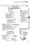
D side U side SS0750 08 C4 PD1 B How to Order Manifold Stations Symbol 02 24 Stations 2 stations 24 stations Cylinder port size Symbol C2 C3 C4 CM N1 N3 NM Port size With o2 One-touch fitting With o3.2 One-touch fitting With o4 One-touch fitting Mixed sizes and with port plug Note) With o1/8" One-touch fitting With o5/32" One-touch fitting Mixed sizes and with port plug Note) Metric Inch Metric Inch Option Note) The maximum number of stations will be different depending on the wiring specifications. Note) Indicate the sizes on the manifold specification sheet in the case of CM and NM. Kit type/Cable length P kit Kit type Symbol Specifications Flat ribbon cable (26P), without cable Flat ribbon cable (26P), with 1.5 m cable Flat ribbon cable (26P), with 3.0 m cable Flat ribbon cable (26P), with 5.0 m cable Flat ribbon cable (20P), without cable Standard station 1 to 12 stations Max. number of stations for special wiring specifications 24 stations Max. number of solenoids 24 1 to 9 stations 18 stations 18 PD0 PD1 PD2 PD3 PDC Note) The maximum number of stations is determined by the total number of solenoids. For mixed single and double wirings, enter “-K” to the order code options. Single 1 Double, Dual 3-port 2 Type of actuation Number of solenoids C8 Symbol 5 6 Specifications 24 VDC 12 VDC How to Order Valves Voltage S07 1 0 5 Base mounted plug-in Specifications Standard External pilot Note) Symbol Nil R Function ・・・ ・・・ B Note 2) D D0 D Note 3) K Note 4) N R Note 5) S Specifications None With back pressure check valve (All sta.) With DIN rail (Rail length: Standard) Without DIN rail (With bracket) With DIN rail Designated length (: Station) Special wiring specifications (Except double wiring) With name plate External pilot Built-in silencer Note 1) When two or more options are specified, indicate them alphabetically. Example) -BKN Note 2) When installing a back pressure check valve on the required station, enter the part number and specify the station position on the manifold specification sheet. Note 3) The available number of stations is larger than the number of manifold stations. Note 4) Indicate the wiring specifications for mixed single and double wirings. Note 5) For details, refer to page 948. . For manifold optional parts, refer to pages 948 to 953. . For manifold exploded view, refer to page 955. Type of actuation Note) For symbol, refer to page 886. Symbol 1 2 A B C Specifications 2-position single 2-position double 4-position dual 3-port (N.C. + N.O.) 4-position dual 3-port (N.O. + N.O.) [Pressure center] 4-position dual 3-port (N.C. + N.C.) [Exhaust center] Note) Not compatible with dual 3-port valves. Note) The P, R port size is o5/16" when the cylinder ports are inch sizes. Symbol Nil C6 C8 N7 N9 Port size With o8 One-touch fitting Note) With o6 One-touch fitting With o8 One-touch fitting With o1/4" One-touch fitting With o5/16" One-touch fitting P, R port size 3 1 2 Stations How to Order Manifold Assembly Specify the part numbers for valves and options together beneath the manifold base part number. SS0750-08C4PD1・・・・・・・・・・ . S0710-5 ・・・・・・・・・・・・・・・・・・・・・・・・ . S0720-5 ・・・・・・・・・・・・・・・・・・・・・・・・ . S07A0-5・・・・・・・・・・・・・・・・・・・・・・・・ . SS0700-10A-1・・・・・・・・・・・・・・