1-p0875-0985-s0700_enü@ü@ü@41 / 112
10ĢbīŃé╔BOOKé╠āyü[āWé╔ł┌ō«éĄé▄éĘ
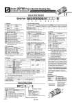
Refer to page 2074 and the Operation Manual for the details of the EX250 Integrated-type (For Output) Serial Transmission System. Please download the Operation Manual via our website,http://www.smcworld.com D side U side 1 2 3 üEüEüEüEüEüE Stations q w r t SS0750 y u i o 08 C4 SDQ e C8 N B How to Order Manifold r Kit type For I/O serial transmission S kit Kit type Specifications Without SI unit DeviceNet. PROFIBUS DP CC-Link CANopen EtherNet/IP. AS-Interface 31 slave, 8 in/8 out, 2 isolated common type AS-Interface 31 slave, 4 in/4 out, 2 isolated common type AS-Interface 31 slave, 8 in/8 out, 1 common type AS-Interface 31 slave, 4 in/4 out, 1 common type Note 3) SD0 SDQ SDN SDV SDY SDZEN SDTA SDTB SDTC SDTD Note 1) The maximum number of stations is determined by the total number of solenoids. For mixed single and double wirings, enter üg-Küh to the order code options. Note 2) For SI unit part number, refer to page 956. Note 3) Up to 24 stations due to the structure of the manifold. Please note the maximum number of stations is 24 for single wiring, too. How to Order Valves How to Order Manifold Assembly Note 1) When two or more options are specified, indicate them alphabetically. Example) -BKN Note 2) When installing a back pressure check valve on the required station, enter the part number and specify the station position on the manifold specification sheet. Note 3) The available number of stations is larger than the number of manifold stations. Note 4) Indicate the wiring specifications for mixed single and double wirings. Note 5) For details, refer to page 948. . For manifold optional parts, refer to pages 948 to 953. . For manifold exploded view, refer to page 955. S w Cylinder port size Symbol C2 C3 C4 CM N1 N3 NM Port size Metric Inch Note) Specify ügMixed sizes and with port plugüh on the manifold specification sheet. With o2 One-touch fitting With o3.2 One-touch fitting With o4 One-touch fitting Mixed sizes and with port plug Note) With o1/8" One-touch fitting With o5/32" One-touch fitting Mixed sizes and with port plug Note) Note) The P, R port size is o5/16" when the cylinder ports are inch sizes. Symbol Nil C6 C8 N7 N9 Port size With o8 One-touch fitting Note) With o6 One-touch fitting With o8 One-touch fitting With o1/4" One-touch fitting With o5/16" One-touch fitting Metric Inch e P, R port size q Stations Symbol 01 24 Note) Stations 1 station 24 stations Note) The maximum number of stations will be different depending on the wiring specifications. üEüEüE üEüEüE t SI unit output polarity Note) Without SI unit (SD0), the symbol is nil. SI unit common Positive common N Negative common EX250 Nil DeviceNet. . PROFIBUS DP . CC-Link . AS-Interface . CANopen . EtherNet/IP. . Series S0700 Plug-in Manifold Stacking Base kit (Serial Transmission) EX250 (For Input/Output) Serial Transmission System Input block (for I/O unit only) Input block type (for I/O unit only) Symbol Nil 0 1 8 Specifications SI unit/Input block: None (SD0) Input block: None Input block: 1 pc. Input block: 8 pcs. Note) Without SI unit (SD0), the symbol is nil. üEüEüE üEüEüE Symbol Nil 1 2 3 Specifications Input block: None M12 2 inputs M12 4 inputs M8 4 inputs (3 pins) Note) Without SI unit (SD0), the symbol is nil. Input block COM. (for I/O unit only) Symbol Nil N Specifications PNP sensor input (Positive common) or without input block NPN sensor input (Negative common) Note) Without SI unit (SD0), the symbol is nil. Option B Note 2) D D0 DŁ Note 3) K Note 4) N R Note 5) S Specifications None With back pressure check valve (All stations) With DIN rail (Rail length: Standard) Without DIN rail (With bracket) With DIN rail Designated length (Ł: Station) Special wiring specifications (Except double wiring) With name plate External pilot Built-in silencer Symbol SS0750-08C4SDQN13N üEüEüEüEüE . S0710-5 üEüEüEüEüEüEüEüEüEüEüEüEüEüEüEüEüEüEüEüE . S0720-5 üEüEüEüEüEüEüEüEüEüEüEüEüEüEüEüEüEüEüEüE . S07A0-5 üEüEüEüEüEüEüEüEüEüEüEüEüEüEüEüEüEüEüEüE . SS0700-10A-1 üEüEüEüEüEüEüEüEüEüE 1 set . Manifold base part no. 3 sets . Valve part no. (Stations 1 to 3) 2 sets . Valve part no. (Stations 4 to 5) 2 sets . Valve part no. (Stations 6 to 7) 1 set . Blanking plate part no. (Station 8)