1-p0875-0985-s0700_en 26 / 112
10秒後にBOOKのページに移動します
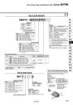
U side 1 2 3 ・・・・・・ Stations D side SS0751 08 C4 PD1 How to Order Manifold Stations Symbol 02 24 Stations 2 stations 24 stations Cylinder port size Symbol C2 C3 C4 N1 N3 Port size With o2 One-touch fitting With o3.2 One-touch fitting With o4 One-touch fitting With o1/8" One-touch fitting With o5/32" One-touch fitting Metric Inch Option Note) The maximum number of stations will be different depending on the wiring specifications. Kit type/Cable length P kit Kit type Symbol Specifications Flat ribbon cable (26P), without cable Flat ribbon cable (26P), with 1.5 m cable Flat ribbon cable (26P), with 3.0 m cable Flat ribbon cable (26P), with 5.0 m cable Flat ribbon cable (20P), without cable Standard station 1 to 12 stations Max. number of stations for special wiring specifications 24 stations Max. number of solenoids 24 1 to 9 stations 18 stations 18 PD0 PD1 PD2 PD3 PDC Note) The maximum number of stations is determined by the total number of solenoids. For mixed single and double wirings, enter “-K” to the order code options. Single 1 Double, Dual 3-port 2 Type of actuation Number of solenoids Symbol 5 6 Specifications 24 VDC 12 VDC How to Order Valves Voltage S07 1 1 5 Base mounted plug-in Specifications Standard External pilot Note) Symbol Nil R Function ・・・ ・・・ Type of actuation Note) For symbol, refer to page 886. Symbol 1 2 A B C Specifications 2-position single 2-position double 4-position dual 3-port (N.C. + N.O.) 4-position dual 3-port (N.O. + N.O.) [Pressure center] 4-position dual 3-port (N.C. + N.C.) [Exhaust center] Note) Not compatible with dual 3-port valves. C8 Note) The P, R port size is o5/16" when the cylinder ports are inch sizes. Symbol Nil C6 C8 N7 N9 Port size With o8 One-touch fitting Note) With o6 One-touch fitting With o8 One-touch fitting With o1/4" One-touch fitting With o5/16" One-touch fitting Metric Inch P, R port size How to Order Manifold Assembly Specify the part numbers for valves and options together beneath the manifold base part number. SS0751-08C4C8PD1・・・・・・ . S0711-5 ・・・・・・・・・・・・・・・・・・・・・・・・ . S0721-5 ・・・・・・・・・・・・・・・・・・・・・・・・ . S07A1-5 ・・・・・・・・・・・・・・・・・・・・・・・・ . SS0700-10A-3 ・・・・・・・・・・・・・・