1-p0875-0985-s0700_en 22 / 112
10秒後にBOOKのページに移動します
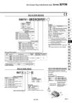
U side 1 2 3 ・・・・・・ Stations D side SS0751 08 C4 FD1 How to Order Manifold Stations Symbol 02 24Note) Stations 2 stations 24 stations Cylinder port size Symbol C2 C3 C4 N1 N3 Port size With o2 One-touch fitting With o3.2 One-touch fitting With o4 One-touch fitting With o1/8" One-touch fitting With o5/32" One-touch fitting Metric Inch Option Note) The maximum number of stations will be different depending on the wiring specifications. Kit type/Cable length F kit Kit type Symbol Specifications D-sub connector (25P), without cable D-sub connector (25P), with 1.5 m cable D-sub connector (25P), with 3.0 m cable D-sub connector (25P), with 5.0 m cable Standard station 1 to 12 stations Max. number of stations for special wiring specifications 24 stations Max. number of solenoids 24 FD0 FD1 FD2 FD3 Note) The maximum number of stations is determined by the total number of solenoids. For mixed single and double wirings, enter “-K” to the order code options. Symbol 5 6 Specifications 24 VDC 12 VDC How to Order Valves Voltage S07 1 1 5 Base mounted plug-in Specifications Standard External pilot Note) Symbol Nil R Function Single 1 Double, Dual 3-port 2 Type of actuation Number of solenoids ・・・ ・・・ Type of actuation Note) For symbol, refer to page 886. Symbol 1 2 A B C Specifications 2-position single 2-position double 4-position dual 3-port (N.C. + N.O.) 4-position dual 3-port (N.O. + N.O.) [Pressure center] 4-position dual 3-port (N.C. + N.C.) [Exhaust center] Note) Not compatible with dual 3-port valves. C8 Note) The P, R port size is o5/16" when the cylinder ports are inch sizes. Symbol Nil C6 C8 N7 N9 Port size With o8 One-touch fitting Note) With o6 One-touch fitting With o8 One-touch fitting With o1/4" One-touch fitting With o5/16" One-touch fitting Metric Inch P, R port size How to Order Manifold Assembly