1-p0875-0985-s0700_en 17 / 112
10秒後にBOOKのページに移動します
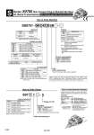
U side 3 1 2 Stations D side S Series S0700 Slim Compact Plug-in Manifold Bar Base kit (Serial Transmission) EX510 Gateway-type Serial Transmission System SS0751 08 C4 SB Option How to Order Manifold Cylinder port size Symbol C2 C3 C4 N1 N3 Port size With o2 One-touch fitting With o3.2 One-touch fitting With o4 One-touch fitting With o1/8" One-touch fitting With o5/32" One-touch fitting Metric Inch Note) For SI unit part number, refer to page 909. How to Order Valves Voltage: 24 VDC Type of actuation S07 1 1 5 Base mounted plug-in Stations Symbol 02 16 Note) Stations 2 stations 16 stations Note) The maximum number of stations will be different depending on the wiring specifications. Note) The P, R port size is o5/16" when the cylinder ports are inch sizes. ・・・ ・・・ Note) For symbol, refer to page 886. Symbol 12 A B C Specifications 2-position single 2-position double 4-position dual 3-port (N.C. + N.O.) 4-position dual 3-port (N.O. + N.O.) [Pressure center] 4-position dual 3-port (N.C. + N.C.) [Exhaust center] Standard station 1 to 8 stations Max. number of stations for special wiring specifications 16 stations Max. number of solenoids 16 Single 1 Double, Dual 3-port 2 Type of actuation Number of solenoids SI unit output polarity Symbol Nil Specifications Positive common N Negative common C8 Symbol Nil C6 C8 N7 N9 Port size With o8 One-touch fitting Note) With o6 One-touch fitting With o8 One-touch fitting With o1/4" One-touch fitting With o5/16" One-touch fitting Metric Inch P, R port size S kit EX510 serial wiring Specifications Standard External pilot Note) Symbol Nil R Function Note) Not compatible with dual 3-port valves. Symbol Nil K Note 2) Specifications None Special wiring specifications (Except double wiring) R Note 3) S External pilot Built-in silencer Note 1) When two or more options are specified, indicate them alphabetically. Example) -KRS Note 2) Indicate the wiring specifications for mixed single and double wirings. Note 3) For details, refer to page 906. . For manifold optional parts, refer to pages 905 and 906. . For manifold exploded view, refer to page 908. How to Order Manifold Assembly Specify the part numbers for valves and options together beneath the manifold base part number. 1 set . Manifold base part no. 3 sets . Valve part no. (Stations 1 to 3) 2 sets . Valve part no. (Stations 4 to 5) 2 sets . Valve part no. (Stations 6 to 7) 1 sets . Blanking plate part no. (Station 8)