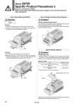
w q w q Tightening torque: 0.5 to 0.7 N・m (a) Element (b) (a) Caution Caution 1) Loosen the clamping screw of the end plate on both sides. 2) Lift side (a) of the manifold base and slide the end plate in the direction of w shown in the figure to remove. Removal 1) Hook side (b) of the manifold base on the DIN rail. 2) Press down side (a) and mount the end plate on the DIN rail. Tighten the clamping screw on side (a) of the end plate. The proper tightening torque for screws is 0.4 to 0.6 Nm. Mounting The connector entry direction can be changed from the top to the side by simply pressing the manual release button. It is not necessary to use the manual release button when switching from the side to the top. Remove the cover from the side of the end plate and remove the old element with a flat blade screwdriver, etc. Caution A silencer element is incorporated in the end plate on both sides of the base. A dirty and choked element may reduce cylinder speed or cause a malfunction. Clean or replace the dirty element. Slim compact plug-in manifold bar base SS0751 Type SS0700-83A Plug-in manifold stacking base SS0750 SS0700-82A Element part no. Element Part No. . Above part number is for a set of ten elements. Plug-in How to Mount/Remove DIN Rail How to Change Connector Entry Direction Built-in Silencer Element Series S0700 Specific Product Precautions 2 Be sure to read before handling. Refer to front matter 53 for Safety Instructions, Pages 3 to 8 for 3/4/5 Port Solenoid Valve Precautions. 974