1-p0759-0802-sz3000_en 44 / 45
10秒後にBOOKのページに移動します
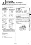
FREE LOCK Light/Surge voltage suppressor Surge voltage suppressor Surge voltage suppressor Light/Surge voltage suppressor Light/Surge voltage suppressor Surge voltage suppressor Surge voltage suppressor [SOL.a] Black (.) COM Red (+) LED (Orange) LED (Green) LED LED Light/Surge Voltage Suppressor Caution Pos. common specifications Single solenoid type Neg. common specifications Single solenoid type Light/Surge voltage suppressor Diode to prevent reverse current Refer to Note. Diode to prevent reverse current Refer to Note. Diode to prevent reverse current Refer to Note. Diode to prevent reverse current Refer to Note. Pos. common specifications Double solenoid, 3 position type, 4 position type Neg. common specifications For double solenoid, 3 position type, 4 position type COM Red (+) [SOL.a] Black (.) Coil Note) Connect so that polarity is matched to the connector’s (+), (.) and A, B and COM indicators. In case of voltage specifications other than 12 or 24 VDC, take care to avoid mistaking polarity, as there is no diode to prevent reverse current. In the event that lead wires are connected in advance, they will be as shown below. Pos. common specifications A (.): Black COM (+): Red B (.): White (No lead wire in case of single solenoid) Neg. common specifications A (+): Black COM (.): Yellow B (+): White (No lead wire in case of single solenoid) Light Indication Changing the Connector Entry Direction Caution When equipped with indicator light and surge voltage suppressor, the light window turns orange when solenoid A is energized, and it turns green when solenoid B is energized. Solenoid A Solenoid B Light A: Orange B: Green Caution To change the connector’s entry direction, press the levers on both sides of the connector, take it off, and change the direction as shown in the drawing. Since lead wires are attached to the connector, excessive pulling or twisting can cause broken wires or other trouble. Also, take care that lead wires are not pinched when installing the connector. If an excessive force is applied on the connector in the LOCK position, the connector block may be damaged. Also, using in such a way that the connector floats in the FREE position, it may cause the lead wire, etc. to break. Thus, refrain from using in these ways. Switch for locking a connector COM Yellow (.) [SOL.a] Black (+) COM Yellow (.) [SOL.a] Black (+) COM Yellow (.) [SOL.a] Black (+) COM Red (+) [SOL.a] Black (.) COM Red (+) [SOL.a] Black (.) [SOL.b] White (.) [SOL.b] White (+) COM Yellow (.) [SOL.a] Black (+) [SOL.b] White (+) Coil Coil Coil Coil Coil Coil Coil Coil Coil LED (Orange) LED (Green) Diode to prevent reverse current Refer to Note. Diode to prevent reverse current Refer to Note. Diode to prevent reverse current Refer to Note. Diode to prevent reverse current Refer to Note. [SOL.b] White (.) Coil Coil 801 Series SZ3000 Specific Product Precautions 3 Be sure to read before handling. Refer to front matter 53 for Safety Instructions and pages 3 to 8 for 3/4/5 Port Solenoid Valve Precautions. SY SJ SY SV SYJ SZ VF VP4 S0700 VQ VQ4 VQ5 VQC VQC4 VQZ SQ VFS VFR VQ7