1-p0759-0802-sz3000_enĀ@Ā@Ā@42 / 45
10ēbĆ„ā…BOOKāŐÉyĀ[ÉWā…ąŕďģāĶā‹ā∑
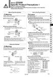
SMC OFF ON Switch [SOL.b] (--) [SOL.a] (--) SX100-40-4S- 6 10 15 20 25 30 50 300mm 600mm 1000mm 1500mm 2000mm 2500mm 3000mm 5000mm SX100-40-4DSX100- 41-4SSX100- 41-4DSZ3160- 5MO-M5 SX100-40-4S-20 ON ON OFF OFF M Type Connector Assembly Part No. Manual Override Operation How to Use Plug Connector Valves with Switches Warning Handle carefully, as connected equipment can be actuated through manual override operation. ūć Non-locking push type Manual override for solenoid A (Orange) Solenoid A Solenoid B Manual override for solenoid B (Green) ūć Push-turn locking slotted type After pushing down, turn in the direction of the arrow. If it is not turned, it can be operated the same way as the non-locking type. Manual override for solenoid A (Orange) Solenoid A Solenoid B Manual override for solenoid B (Green) Caution When locking the manual override with the push-turn locking slotted type, be sure to push it down before turning. Turning without first pushing it down can cause damage to the manual override and other trouble such as air leakage, etc. ON position OFF position Electric circuit diagram (With positive common and light/surge voltage suppressor) Normal operating condition. Switching of valve is based on an electric signal from the connector. The valve coil is kept in a deenergized state even when there is an electric signal from the connector. Switch COM (+) Coil Coil 1. Attaching and detaching connectors Caution When attaching and detaching a connector, first shut off the electric power and the air supply. Also, crimp the lead wires and sockets securely. ūĎTo attach a connector, hold the lever and connector unit between your fingers and insert straight onto the pins of the solenoid valve so that the leverĀfs pawl is pushed into the groove and locks. ūĎTo detach a connector, remove the pawl from the groove by pushing the lever downward with your thumb, and pull the connector straight out. Cover Concave Pin Lever Polarity indicator connector Hook Socket Model no. DXT170-71-1 Lead wire 2. Crimping of lead wires and sockets Peel 3.2 to 3.7 mm of the tip of lead wire, enter the core wires neatly into a socket and crimp it with a special crimp tool. Be careful so that the cover of lead wire does not enter into the crimping part. (Please contact SMC for the dedicated crimping tools.) Socket Lead wire Core wire crimping area Crimping area Hook Insulation 0.2 to 0.33 mm2 Max. cover diameter: o1.7 mm Core wire 3. Attaching and detaching lead wires with sockets ūĎAttaching Insert the sockets into the square holes of the connector (with + and . indication), and continue to push the sockets all the way in until the lock by hooking into the seats in the connector. (When they are pushed in, their hooks open and they are locked automatically.) Then confirm that they are locked by pulling lightly on the lead wires. ūĎDetaching To detach a socket from a connector, pull out the lead wire while pressing the socketĀfs hook with a stick having a thin tip (approx. 1 mm). If the socket is used again, spread the hook outward. Socket Lead wire Hook Insert into these square holes Connector ūć Plug connector lead wire lengths Plug connector lead wires have a standard length of 300 mm, however, the following lengths are also available. How to Order Positive common specifications Negative common specifications