1-p0759-0802-sz3000_en 38 / 45
10秒後にBOOKのページに移動します
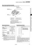
How to Order Valve Manifold Assembly Ordering example (SZ3000, positive common with power supply terminals) SS5Z3-60GD2-05U・・・・・・・・・1set (Manifold part number) . SZ3160-5LOZ-C6・・・・・・・・・・・・2sets (Single solenoid part no.) . SZ3260-5LOZ-C6・・・・・・・・・・・・3sets (Double solenoid part no.) Double solenoid SZ3260-5LOZ-C6 (3sets) Single solenoid SZ3160-5LOZ-C6 (2sets) Manifold SS5Z3-60GD2-05U SUP/EXH block (U side mounting) 1 2 3 Stations D side U side FREE LOCK Type 60GD PC wiring Manifold Electrical Wiring . This circuit has double wiring specifications for up to 8 stations. Since the usable number of solenoids differs depending on the manifold type, refer to the table below. In the case of single solenoids, connect to SOL. A. Furthermore, when wiring is specified on a manifold specification sheet, connections are made without skipping any connectors, and signals A for single and A, B for double are in order 20 傻 18 傻 16 傻 14, etc. . Stations are counted from D side (Connector side) as the 1st one. . Since terminal numbers are not indicated on the flat cable, use the triangle mark as a reference for wiring. Model A, B port Porting specification Port size Flat ribbon cable type 60G Plug-in type Common SUP, EXH Valve Lateral C8 C4, C6, M5 2 to 16 stations Flat ribbon cable connector Socket: 20 pins MIL type with strain relief Conforming to MIL-C-83503 Weight W(g) Note 2) n1: Stations n2: Number of SUP/EXH blocks m: Weight of DIN rail Location Direction P, R port A/B port Manifold P(SUP)/R(EXH) system Valve stations Note 1) Applicable connector Manifold Specifications W = 3.2n1 + 53n2 + m + 126.5 The asterisk denotes the symbol for assembly. Prefix it to the part nos. of the solenoid valve, etc. . Stations are counted from D side as the 1st one. . Indicate the valves to be attached below the manifold part number, in order starting from station 1 as shown in the drawing. When entry of part numbers becomes complicated, indicate on the manifold specification sheet. Note 1) This manifold is applicable to up to 16 solenoid valves. When many valves are operated simultaneously, use B type (SUP/EXH both sides), applying pressure to the P ports on both sides and exhaust from the R ports on both sides. Note 2) The weight W is the value for the manifold only. To obtain the weight with solenoid valves attached, add the weight of the solenoid valve stations to that of the manifold. For details about the DIN rail weight, refer to the separate catalog CAT.ES11-75. 4 Station SOL.a 16 Station 5 Station SOL.b (Double solenoid (Dual body type)) 3 Station SOL.a (Single solenoid) 2 Station SOL.a (Single solenoid) 1 Station SOL.a (Single solenoid) 1,2 Power supply terminal 3,4 Terminal no. 5 7 9 11 13 15 17 19 6 8 10 12 14 16 18 20 795 Cassette Type Manifold Series SZ3000 SY SJ SY SV SYJ SZ VF VP4 S0700 VQ VQ4 VQ5 VQC VQC4 VQZ SQ VFS VFR VQ7