1-p0759-0802-sz3000_en 10 / 45
10秒後にBOOKのページに移動します
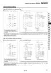
Positive common Negative common Station 1 SOL.b SOL.a Station 2 SOL.b SOL.a Station 11 SOL.b SOL.a Station 12 11 SOL.b SOL.a 12 25 24 15 2 14 1 13 Common Power supply terminal Station 20 3 SOL.b Station 5 SOL.a Station 4 15 2 SOL.a Station 3 SOL.a Station 2 14 1 SOL.a Station 1 Unused terminal 11 24 12 13 25 24 23 Positive pin (Common) Negative pin Power supply terminal Station 20 3 SOL.b Station 5 SOL.a Station 4 15 2 SOL.a Station 3 SOL.a Station 2 14 1 SOL.a Station 1 23 Unused terminal 11 24 12 13 25 24 Positive pin Negative pin (Common) Station 12 SOL.b SOL.a Station 11 SOL.b SOL.a Station 2 SOL.b SOL.a Station 1 SOL.b SOL.a 21 Triangle mark Common 25 26 23 24 22 3 4 1 2 Power supply terminal Station 20 21 Unused terminal 20 Triangle mark Positive pin (Common) Negative pin 25 26 23 24 22 5 6 3 4 1 2 SOL.a Station 4 SOL.b Station 5 SOL.a Station 1 SOL.a Station 2 SOL.a Station 3 Power supply terminal Station 20 21 Unused terminal 20 Triangle mark Positive pin Negative pin (Common) 25 26 23 24 22 5 6 3 4 1 2 SOL.a Station 4 SOL.b Station 5 SOL.a Station 1 SOL.a Station 2 SOL.a Station 3 Positive common Negative common 傱 Without Power Supply Terminal 傱 With Power Supply Terminal Type 60F D-sub Connector Type (25 pins) 傱 Without Power Supply Terminal 傱 With Power Supply Terminal Type 60P Flat Ribbon Cable Type (26 pins) . The common polarity should be the same as the common specifications of the valve to be used. . The maximum number of stations that can be accommodated is 20 manifold stations, with up to 24 solenoids. . The maximum number of stations that can be accommodated is 20 manifold stations, with up to 21 solenoids. . The circuits above are for the double wiring specifications with up to 10 or 12 stations. Connect to SOL.A in the case of a single solenoid. Moreover, when wiring instructions are given on a manifold specification sheet, the “A” signal for single and the “A, B” signals for double should be wired in order 1, 14, 2, 15......etc., without skipping or leaving any connectors remaining. . Stations are counted from D side as the 1st one. . The common polarity should be the same as the common specifications of the valve to be used. . The maximum number of stations that can be accommodated is 20 manifold stations, with up to 25 solenoids. . The maximum number of stations that can be accommodated is 20 manifold stations, with up to 22 solenoids. . The circuits above are for the double wiring specifications with up to 11 or 12 stations. Connect to SOL.A in the case of a single solenoid. Moreover, when wiring instructions are given on a manifold specification sheet, the “A” signal for single and the “A, B” signals for double should be wired in order 1, 2, 3, 4......etc., without skipping or leaving any connectors remaining. . Stations are counted from D side as the 1st one. . Since terminal numbers are not indicated on the flat cable, use the triangle mark as a reference for wiring. 767 Cassette Type Manifold Series SZ3000 Manifold Electrical Wiring SY SJ SY SV SYJ SZ VF VP4 S0700 VQ VQ4 VQ5 VQC VQC4 VQZ SQ VFS VFR VQ7