1-p0527-0653-sv1000_en 87 / 128
10秒後にBOOKのページに移動します
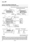
Dimensions: Series SV2000 for Flat Ribbon Cable L1 L2 L3 L4 L5 L n 2 148 137.5 106.4 24 80 5 185.5 175 154.4 19 128 6 210.5 200 170.4 23.5 144 7 223 212.5 186.4 21.5 160 8 235.5 225 202.4 20 176 9 248 237.5 218.4 18 192 10 273 262.5 234.4 22.5 208 11 285.5 275 250.4 21 224 12 298 287.5 266.4 19 240 13 323 312.5 282.4 23.5 256 14 335.5 325 298.4 22 272 15 348 337.5 314.4 20 288 16 360.5 350 330.4 18.5 304 17 385.5 375 346.4 23 320 18 398 387.5 362.4 21 336 19 410.5 400 378.4 19.5 352 20 435.5 425 394.4 24 368 4 173 162.5 138.4 20.5 112 3 160.5 150 122.4 22.5 96 L Dimension n : Stations P 1 3/5 E 3/5 B A 2 4 B A 2 4 B A 2 4 B A 2 4 B A 2 4 (Rail mounting hole pitch: 12.5) (Pitch) A B A B A B A B A B A B A B P 1 E P 1 3/5 E 3/5 B A 2 4 B A 2 4 B A 2 4 B A 2 4 B A 2 4 P 1 E Connector case Release lever (Both sides) 4 x o5.3 Light/Surge voltage suppressor PE X PE X 10PG (20 pins) 10PH (10 pins) 12 52.5 63.5 115.5 L5 20.5 9.2 25.2 P=16 17.5 (7.5) (41.6) 66.4 (18.9) L2 L1 5 L3 (L4) (4.9) 5.4 34.9 49.9 63.5 11.8 11.9 30.6 29.6 12.2 5.5 35 11.4 58.9 109.4 20.4 9.9 (5.3) 53.4 15.8 9.5 97.5 102.9 8 Tie-rod base manifold : SS5V2-10 D - Stations UDB C4, N3 C6, N7 C8, N9 (S, R, RS)- (-D) P PG PH 12 When P, E port outlets are indicated on the U side or D side, the P, E ports on the opposite side are plugged. External pilot port positions and silencer discharge port positions are the same as P, E port outlet positions. One-touch fitting [PE: Pilot EXH port] Applicable tubing O.D.: o4 o5/32" One-touch fitting [X: External pilot port] Applicable tubing O.D.: o4 o5/32" One-touch fitting [1(P), 3/5(E) port] Applicable tubing O.D.: o10 o3/8" One-touch fitting [4(A), 2(B) port] Applicable tubing O.D.: o4, o5/32" o6, o1/4" o8, o5/16" U side D side (For mounting) Applicable connector: 26 pins MIL type (Conforming to MIL-C-83503) Triangle mark position (Lateral connector entry) Silencer (Air discharge port) (Built-in silencer specifications) DIN rail holding screw (For DIN rail mounting) Manual override Press and turn for the (locking type. 4(A) port side: Orange 2(B) port side: Green ) Triangle mark position Triangle mark position Refer to page 600 (compliant for D-sub connector) for dimensions with interface regulator and individual SUP/EXH spacer. Applicable connector: 20 pins MIL type (Conforming to MIL-C-83503) Applicable connector: 10 pins MIL type (Conforming to MIL-C-83503) (Station n) (Station 1) (DIN rail dimension) Series SV With External Pilot Specifications 612