1-p0527-0653-sv1000_en 114 / 128
10秒後にBOOKのページに移動します
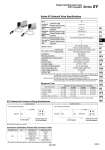
. This connector is a female connector for q relay output module and w single unit/sub-plate. Connector size M12 pin 4 Manufacturer Correns Corp. OMRON Corp. Azbil Corp. Hirose Electric Co., Ltd. DDK Ltd. Applicable series VA-4D XS2 PA5-41 HR24 CM01-8DP4S Connection Destination (Female Side) Connector Cable Series SV Solenoid Valve Specifications Fluid Ambient and fluid temperature (°C) Manual override Pilot exhaust method Lubrication Mounting orientation Impact/Vibration resistance (ms2) Enclosure Electrical entry Coil rated voltage Allowable voltage fluctuation Power consumption (W) Surge voltage suppressor Indicator light Air 0.15 to 0.7 0.1 to 0.7 0.2 to 0.7 .100 kPa to 0.7 0.25 to 0.7 .10 to 50 (No freezing. Refer to page 5.) 5 3 Non-locking push type Push-turn locking slotted type Common exhaust type for main and pilot valve Pilot valve individual exhaust Not required Unrestricted 150/30 (8.3 to 2000 Hz) IP67 (Based on IEC60529) M12 waterproof connector 24 VDC, 12 VDC ±10% of rated voltage 0.6 (With indicator light: 0.65) Zener diode LED 2 position single 4 position dual 3 port valve 2 position double 3 position Operating pressure range 2 position single, double 3 position 2 position single, double 4 position dual 3 port valve 3 position Internal pilot operating pressure range (MPa) External pilot operating pressure range (MPa) Max. operating frequency (Hz) Internal pilot External pilot Note) Impact resistance: No malfunction occurred when it is tested with a drop tester in the axial direction and at the right angles to the main valve and armature in both energized and de-energized states every once for each condition. (Values at the initial period) Vibration resistance: No malfunction occurred in a one-sweep test between 45 and 2000 Hz. Test was performed at both energized and de-energized states in the axial direction and at the right angles to the main valve and armature. (Values at the initial period) Note) Based on dynamic performance test, JIS B 8375-1981. (Coil temperature: 20°C, at rated voltage) Type of actuation 2 position single 2 position double 3 position 4 position dual 3 port valve SV1000 11 or less 10 or less 18 or less 15 or less SV2000 25 or less 17 or less 29 or less 33 or less SV3000 28 or less 26 or less 32 or less . SV4000 40 or less 40 or less 82 or less . Response Time Response time (ms) (at the pressure of 0.5 MPa) Single solenoid Double solenoid M12 Waterproof Connector Wiring Specifications Note) Solenoid valves have no polarity. Series SV Single Valve/Sub-plate Type IP67 Compliant Coil 2 3 (COM) Coil 4 Coil 4 3 (COM) 4 pin connector (M12) plug 4 pin connector (M12) plug Circuit diagram Circuit diagram Solenoid Solenoid A Solenoid B Solenoid valve side pin wiring diagram 2 1 3 4 2 1 3 4 Solenoid valve side pin wiring diagram 639 SY SJ SY SV SYJ SZ VF VP4 S0700 VQ VQ4 VQ5 VQC VQC4 VQZ SQ VFS VFR VQ7 B